So now all of the pieces have come together!

My crafting diary
So now all of the pieces have come together!

So my first print of the new legs got ruined because of two level shifts. But Eric was nice enough to restart the print. So another 48 hours and 200g of plastic later I could go an pick up the finished print. I found there was some warping on some of the axels, but nothing that hinders their function.
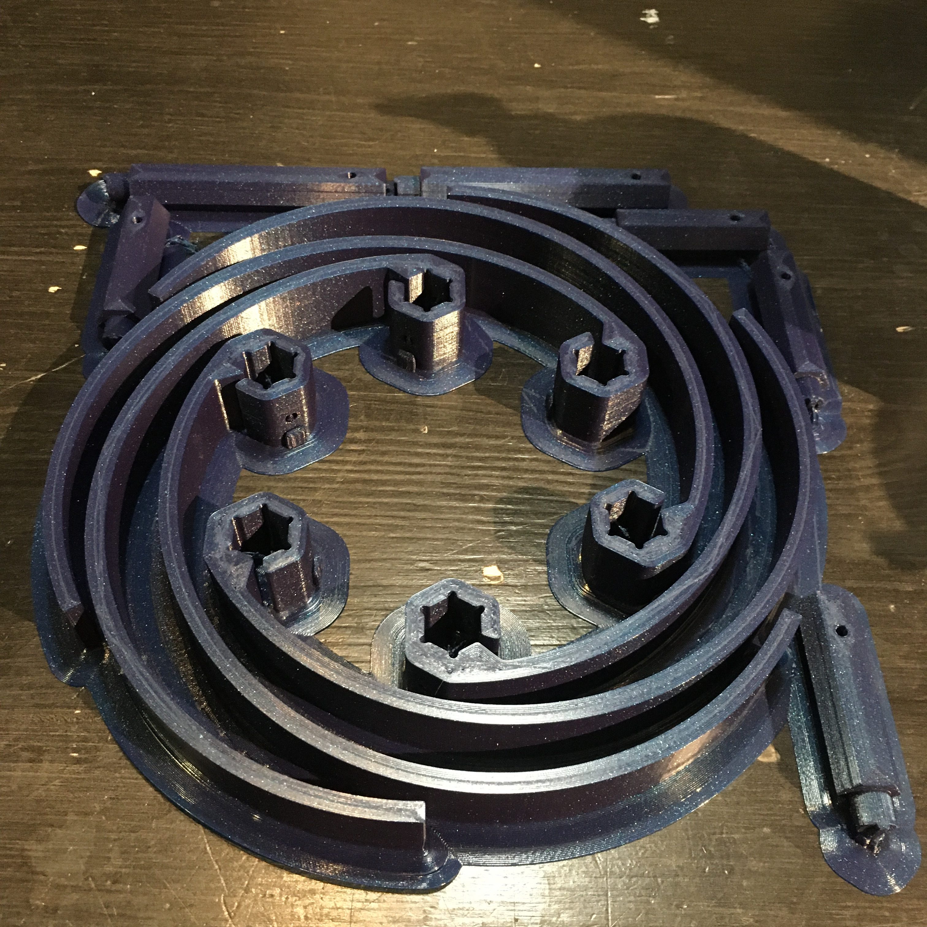
A little cleanup later, and we have a pretty set of parts. Here I haven’t drilled out the support structures inside of the holes, though. That turned out to be rather hard and I have broken one so far by drilling straight through it.
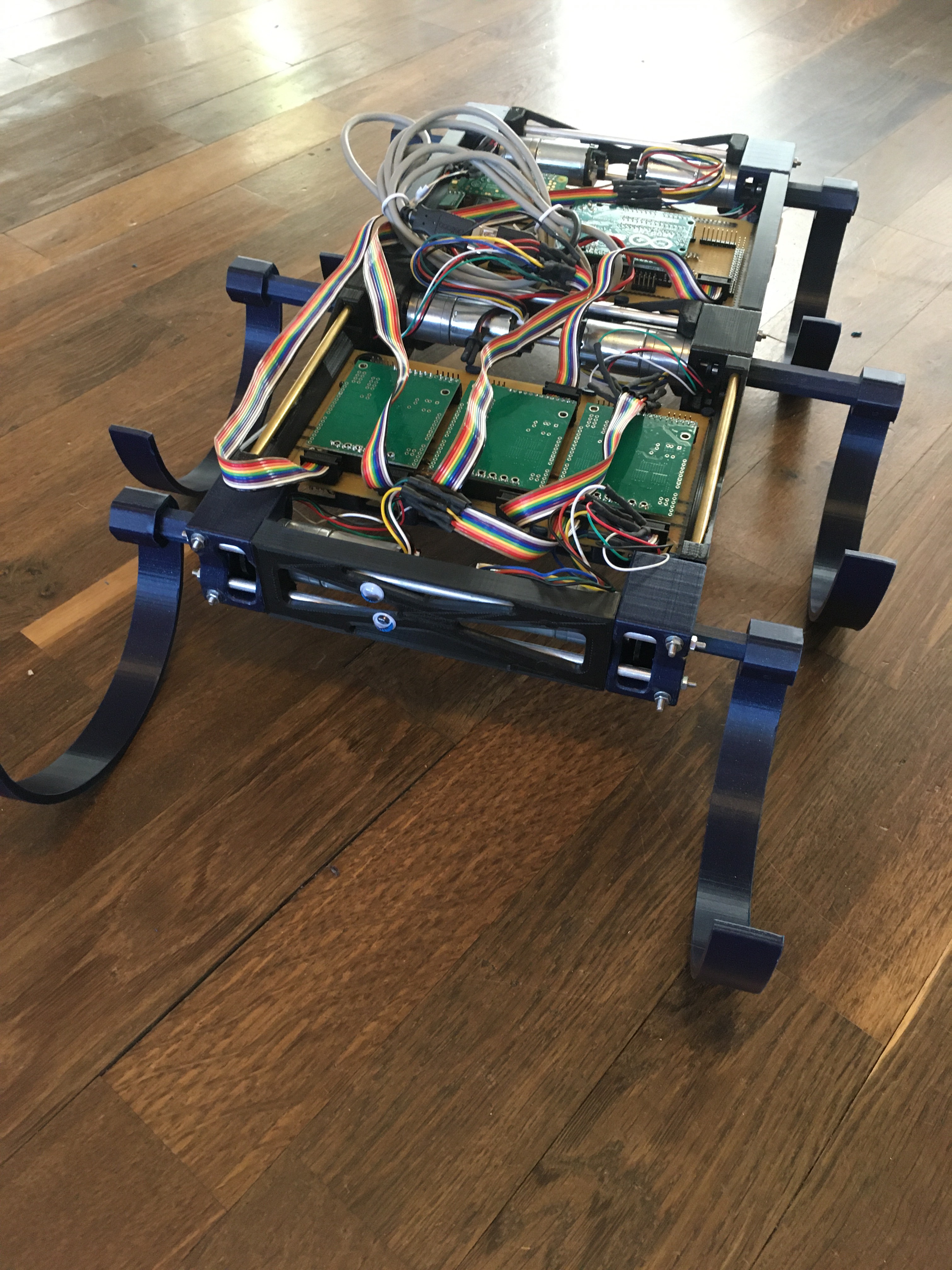
And here we have it. Three complete leg joints with legs and everything (Well, the legs aren’t fastened, but you get the idea)
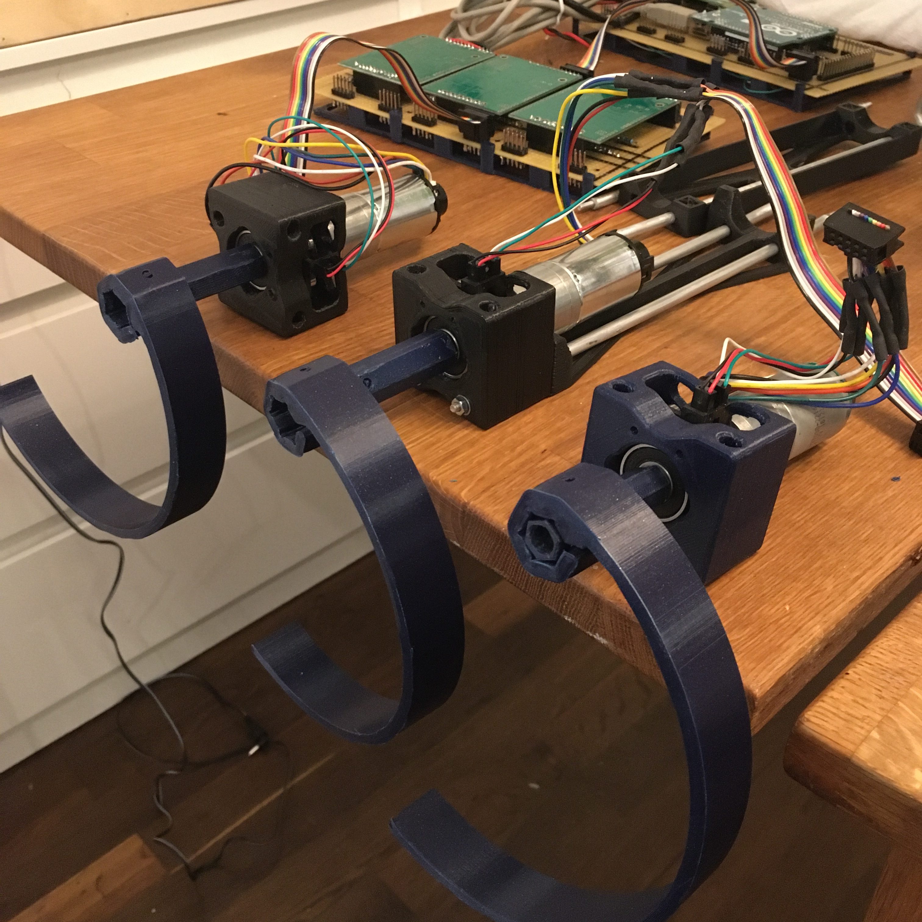
Now, these are three leg joints with short axels. What about the long axels? Well, it turns out that if you drill a hole deep enough, your screwdrivers don’t work……

Yeah, so I had some setbacks. When putting it all together, I noticed that 3 of the legs moved nicely, but the other three did not move well at all and I could see the plastic flex as the motors turned.
I had clearly made one of the simple beginner mistakes. I had designed a stiff design that required tight tolerances, without having the manufacturing techniques to get tight tolerances. The holes in the leg axels are simply drilled and that does not give me a round and precise enough hole for the axels to be perfectly colinear with the shaft. Then I tighten the set screw and I get a stiff and crooked machine. Not good at all.
So back to the shop for some experimentation. My first idea was to drill a small 2mm hole in the motor shafts and put a pin through there. That pin could then have gone through the setscrew holes in the axel externders. That would ave probably worked really well, except for the fact that the moror shafts are cearly made out of a super hard metal, so my brand new HSS drill only started smoking, made the wrong kind of noise and then snapped.
What do do?
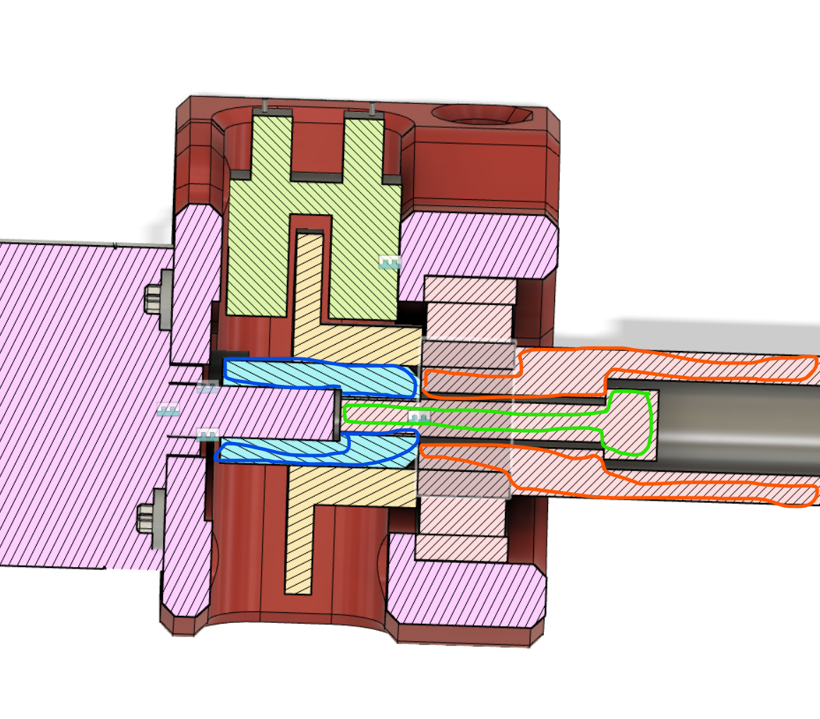
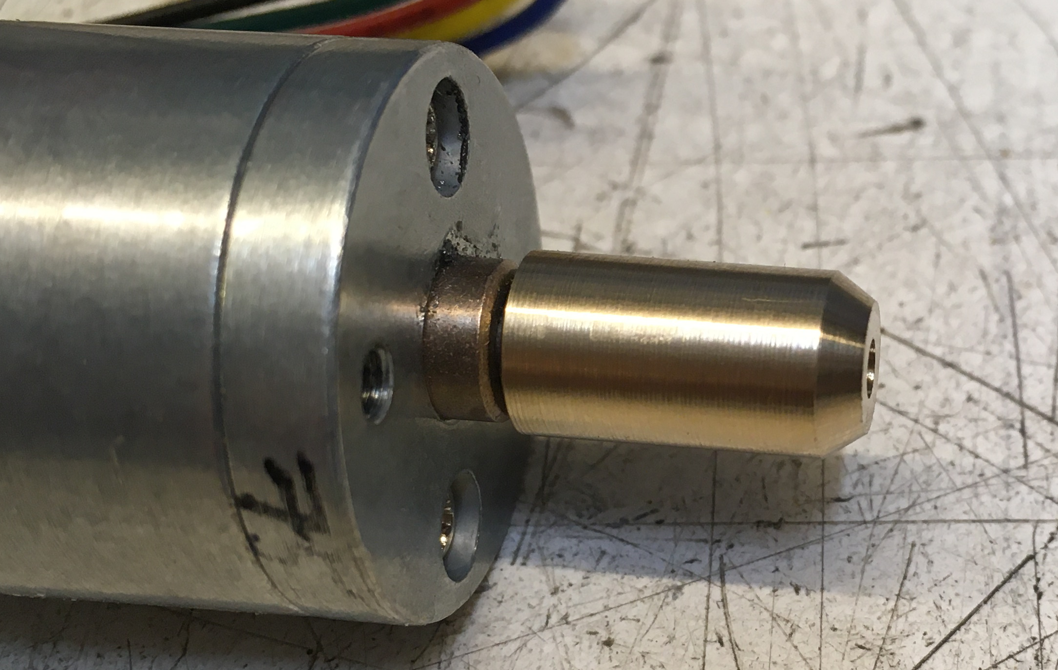
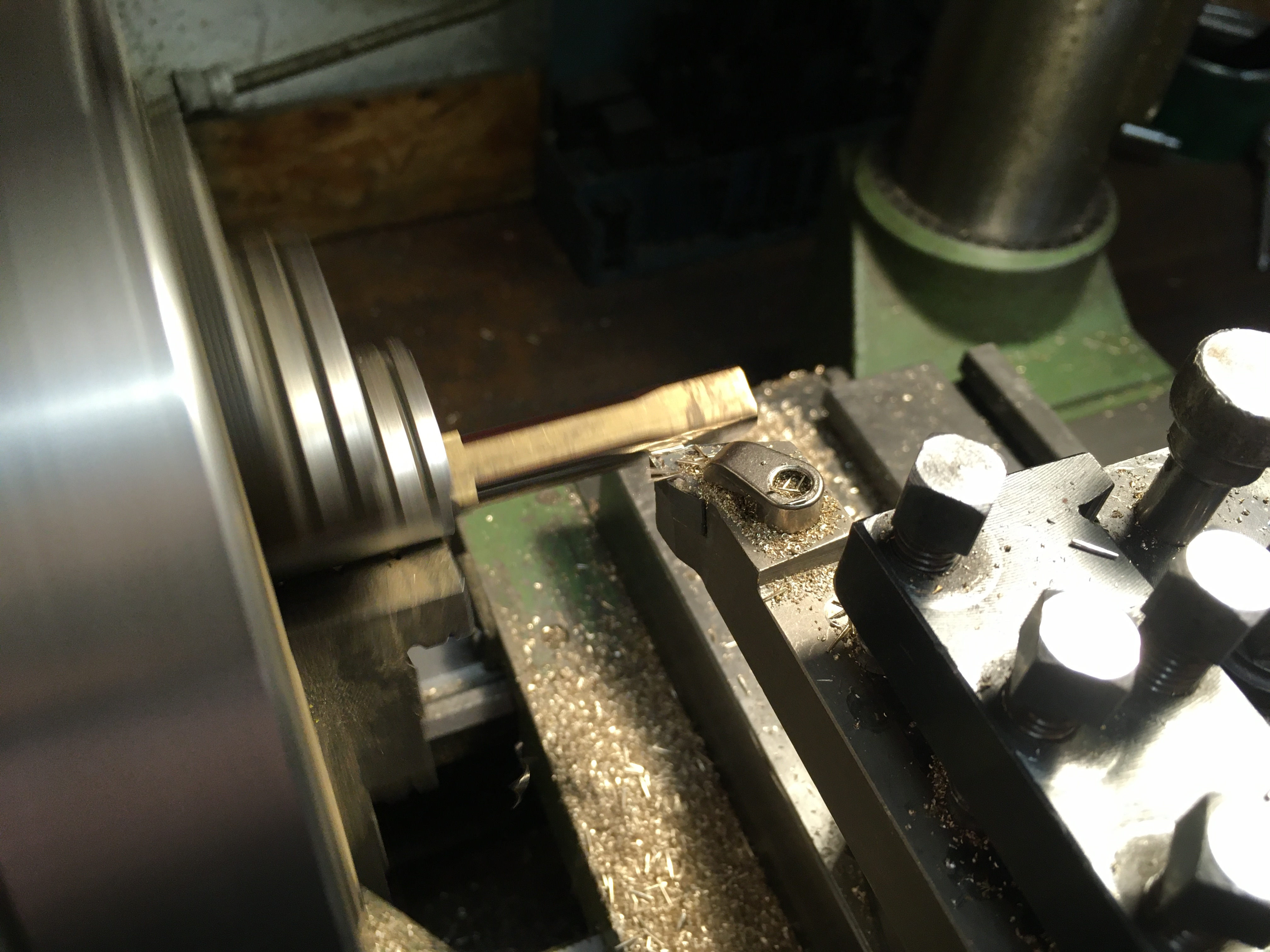
Well, back to design. After some thinking about mixing metal and plastig to get the stiffness I needed to grip the D-shaft of the motors, but then use plastic to get some flexibility. After some back and forth, here is where I landed. A brass collar around the motor shaft. A rather hefty plastic axel. And a m3x20 screw to bind it all together. A key in the brass collar and plastic axel should give some additional grip as the motor spins.
Here is the collar right out of the lathe. Stopscrew holes and the key for the axel are not done here. But I did those right after taking the picture.
Yesterday I wrapped the controller board as well. Now, all connections are in place on both boards.
I checked for shorts and found one, so I hope that was the only one….

I also collected the 3d-printed covers to protect the wires above. A single quick move with a screwdriver could really mess things up otherwise….
And with that, I am starting to put everything together.
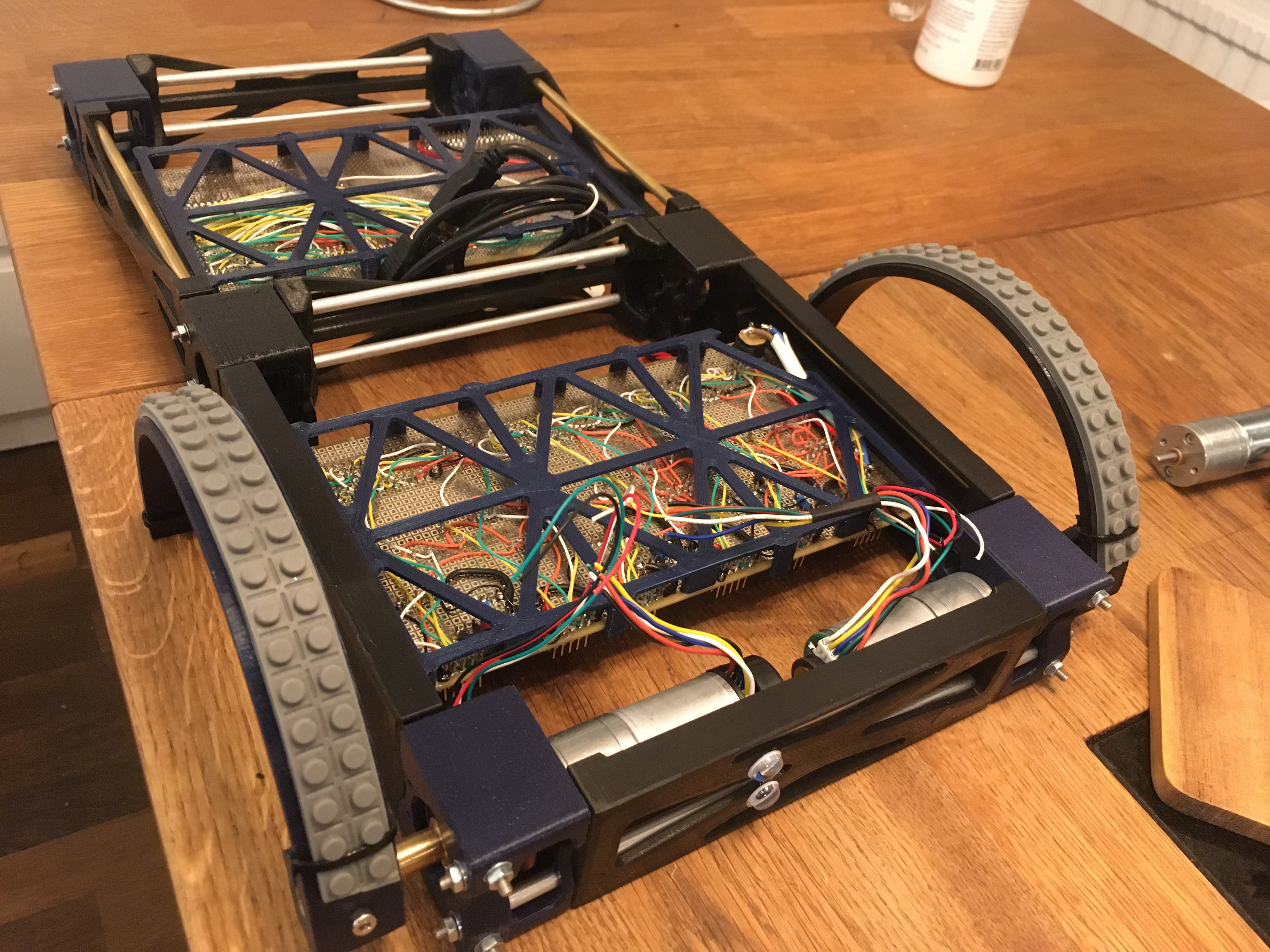

So now I will slowly connect things one by one to see that it all works and nothing is broken…..
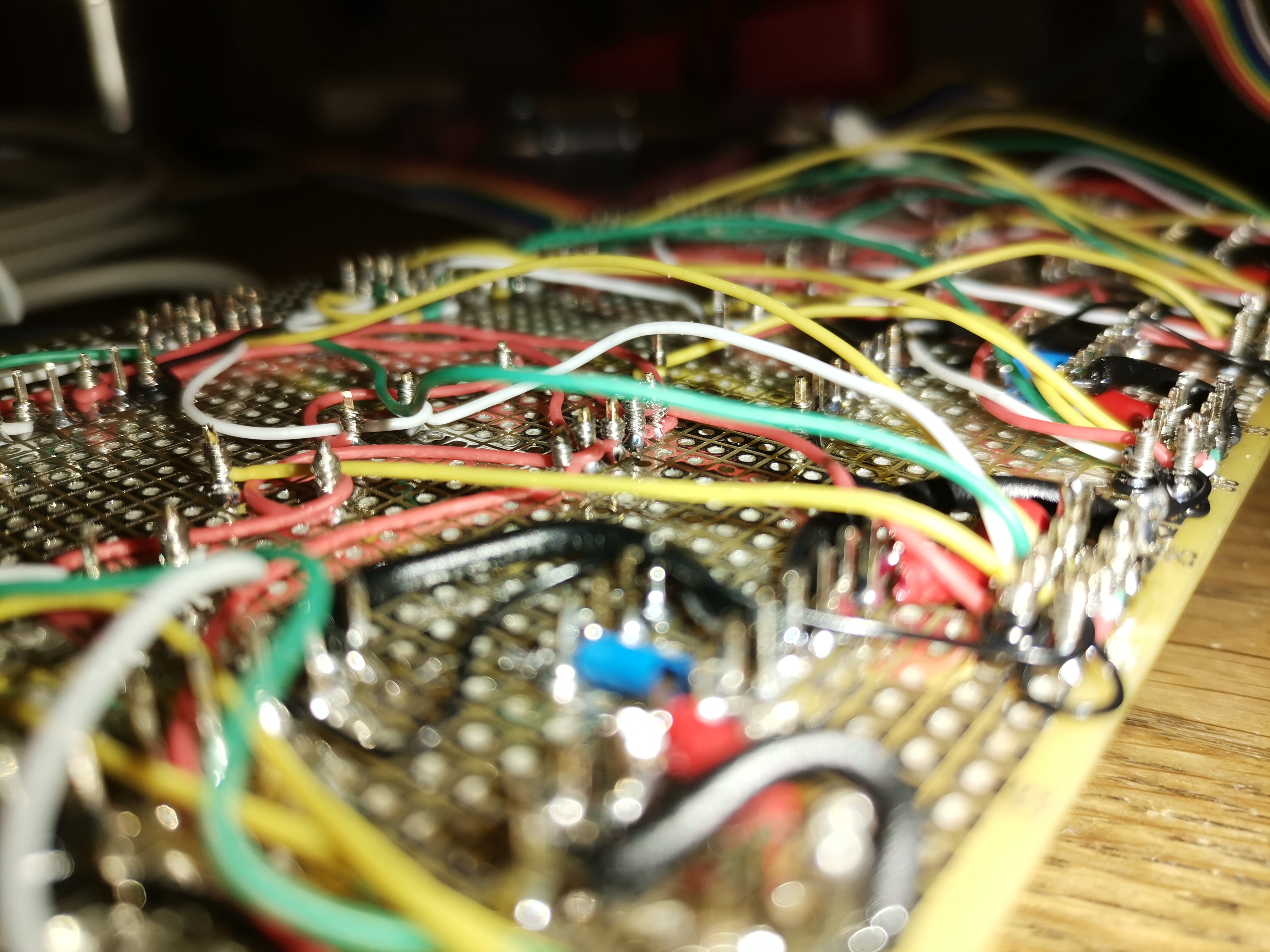
So I wrapped the entire driver board, and it worked perfectly on the first test. So now I have a board with three dual-driver cards that can power and controll a total of 6 motors complete with all of their detectors.
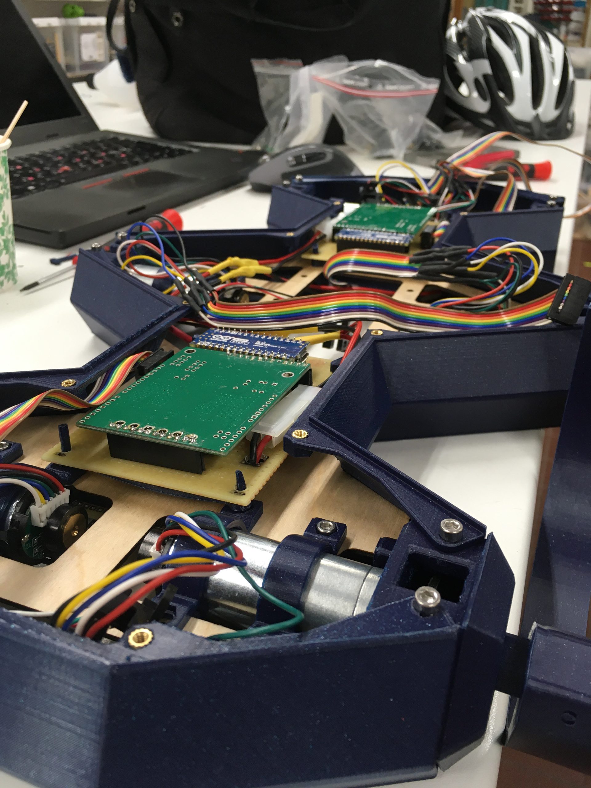
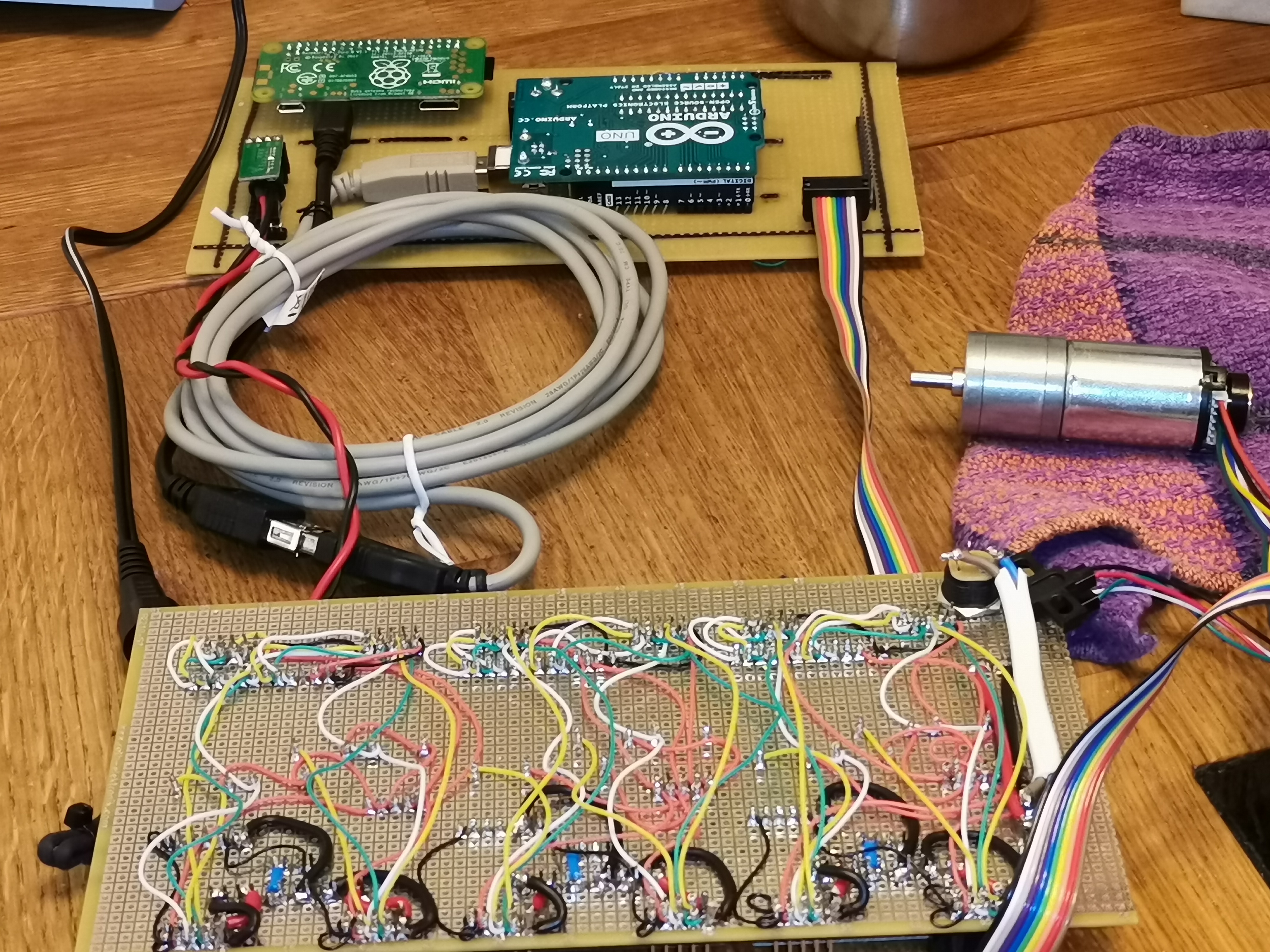
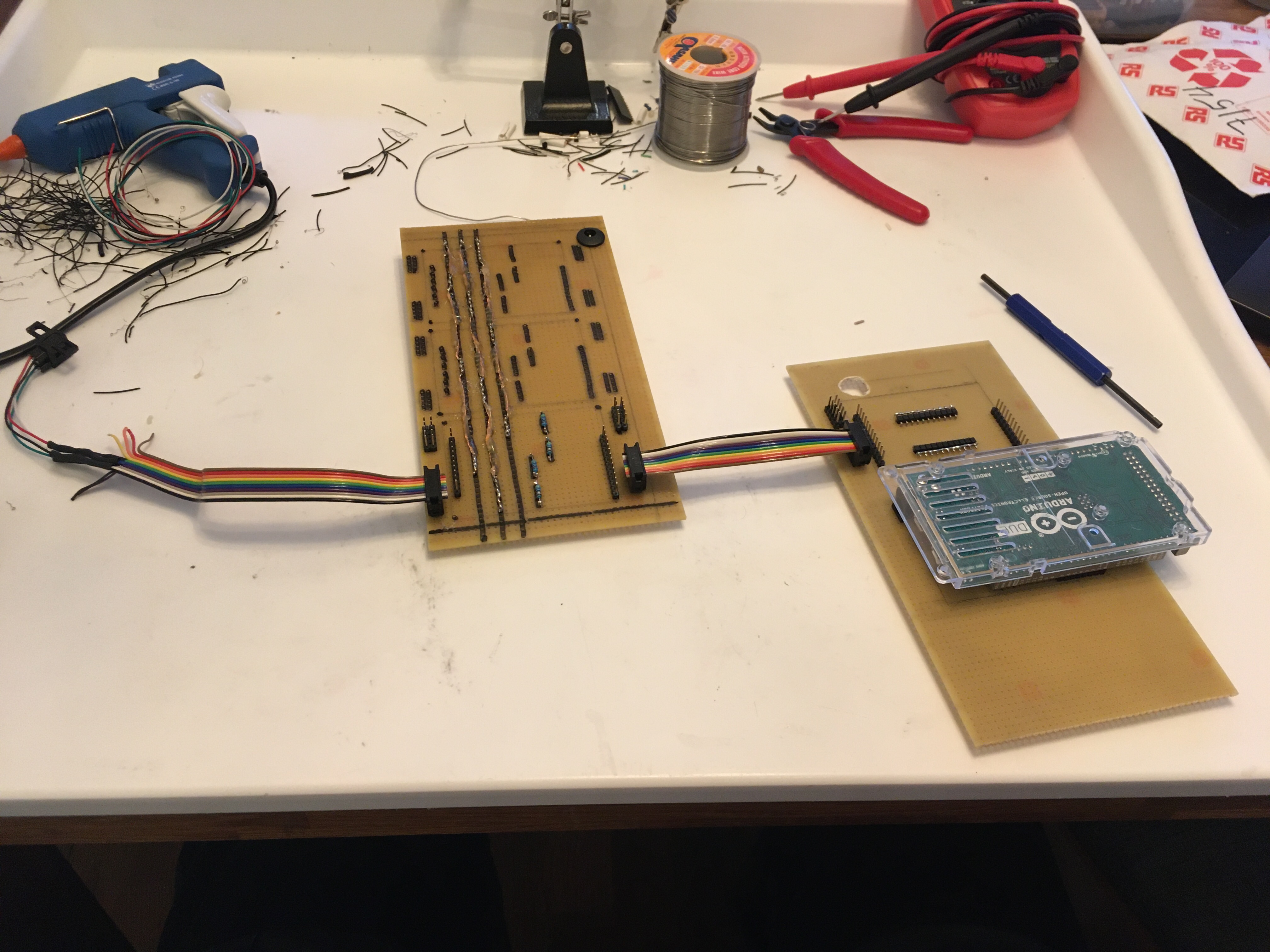
Also, I don’t think I have uploaded a picture of the entire development setup. In the foreground, you see the backside of the powerboard with all of its wires. In the background, you see another board with two mini-computers on it. One is an Arduino that I use for the real-time stuff. Here you see an Uno mounted, which does not have enough pins to control all of the 6 motors (7 pins per motor means 42 pins, of which 6 analog-in and 6 PWM). So the plan is to place my Due there to be able to controll all motors at the same time.
But the real nice detail is the tiny little Raspberry Pi Zero W you see furthest away. In that super-tiny board is a completre computer, including Wifi. So I simply installed my development environment on there. As soon as it coot sup, it connects to my home WiFi and I can just telnet in and continue where I left off. No need to maintain a dev environment on my laptops (I have 2). Everythingis just there, guaranteed to be perfectly compatible.
So lots of tiny pieces on the way now.
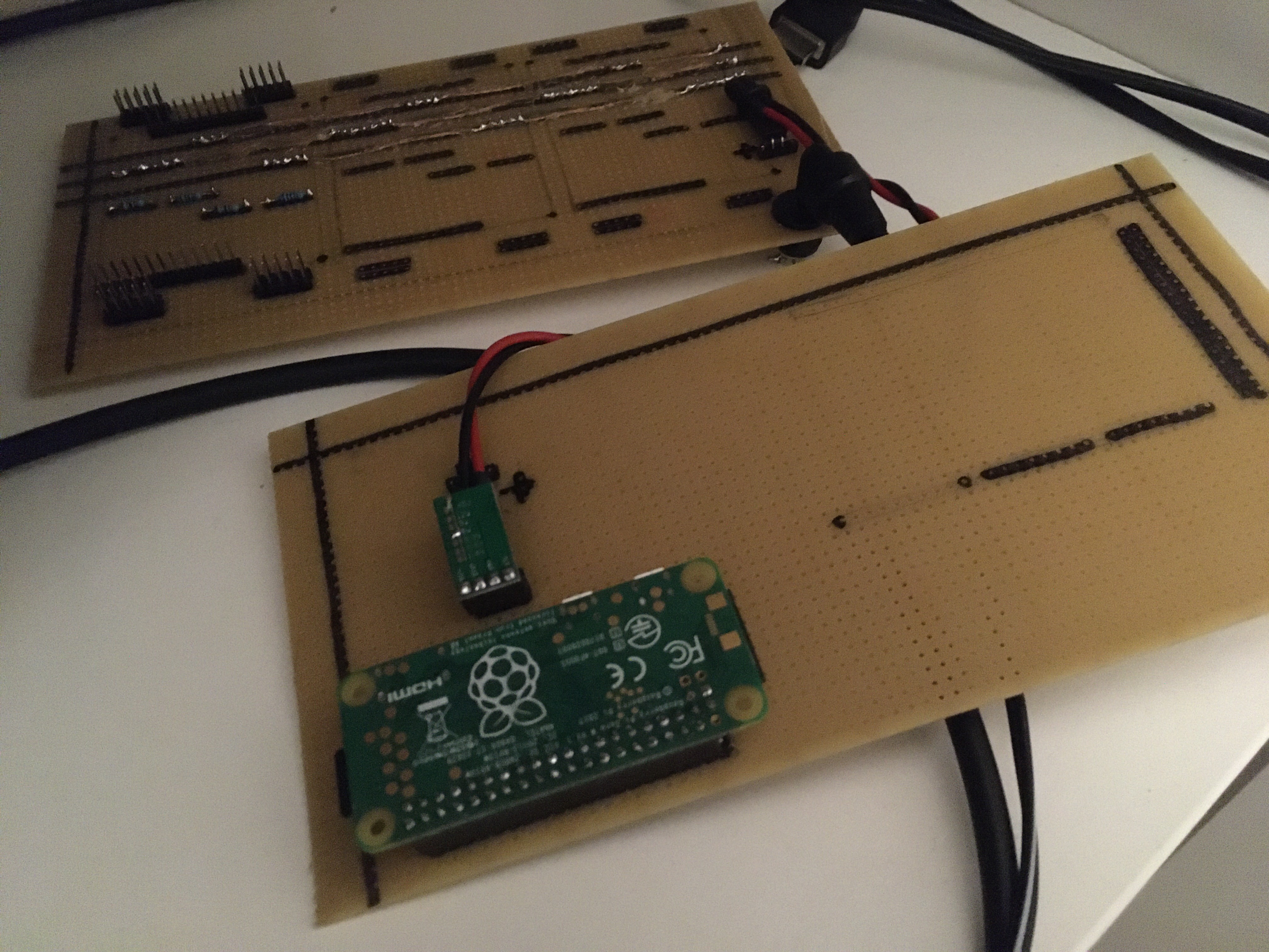
First up I realized that a Resperry Pi Zero W is super tiny and allows me to maintain an entire development environement onboard. As soon as it boots, it connects to the internet and I can ssh directly to it. If I install platformio and a console text editor then I can keep the entire development environment onboard.
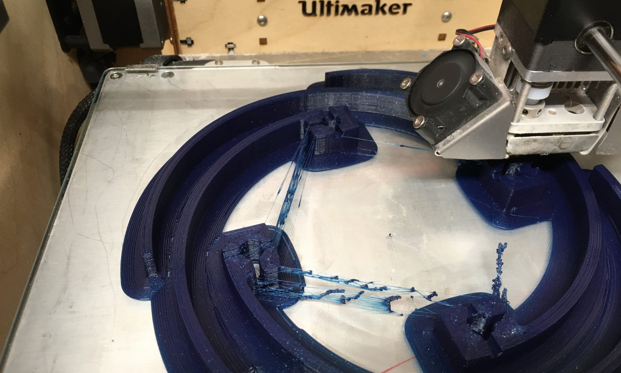
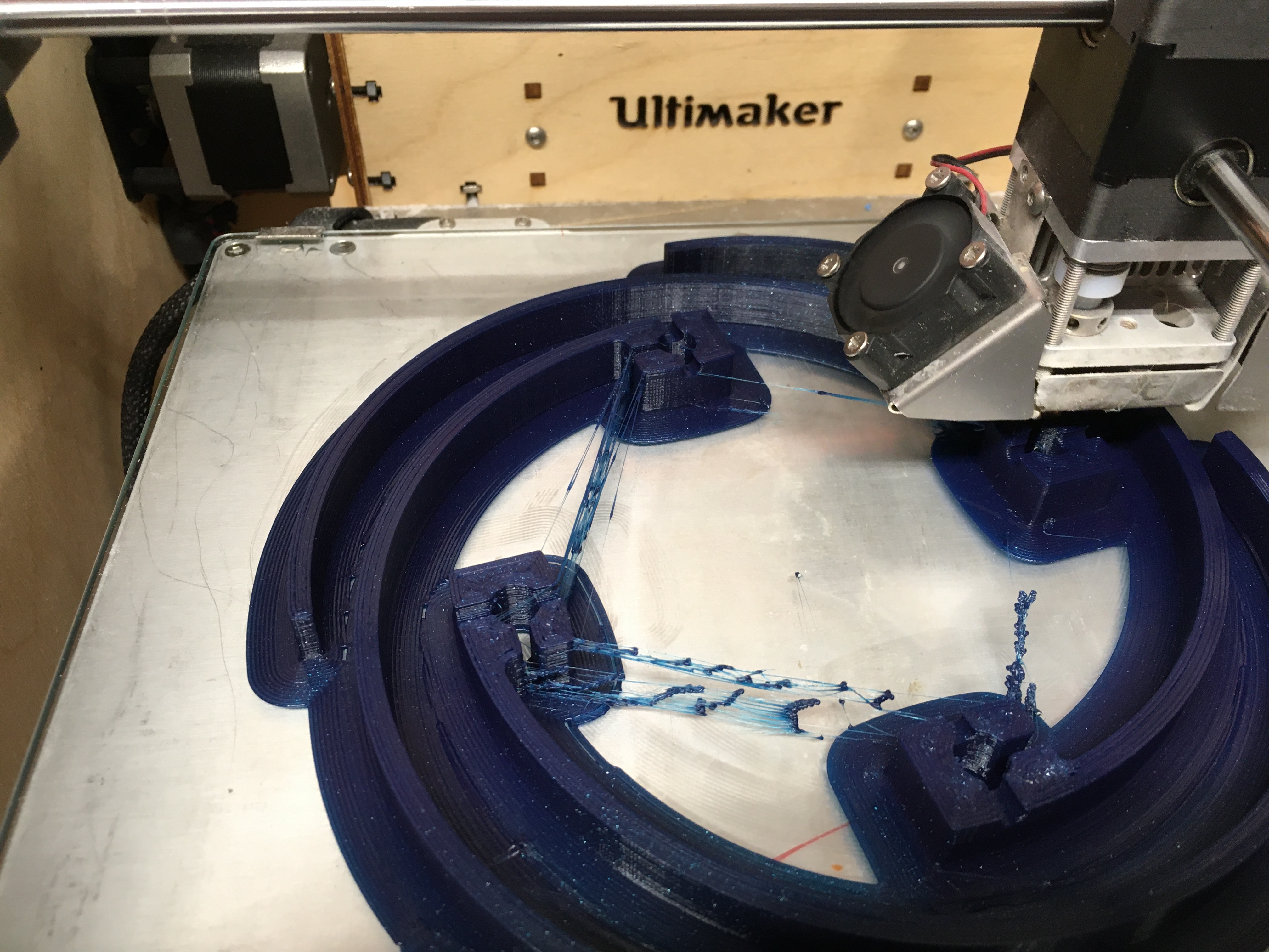
Second, I have a complete set of breaker plates being printed.
And on the side, I fixed the toy excavator. The gas for the MAG was almost out, and I could not find the angle grinder to clear off all of the paint, so the result was horrible. Or maybe it is just that I really suck at welding…..

Fortunately, I found the angle grinder once I was done and could polish away the worst of the sins.
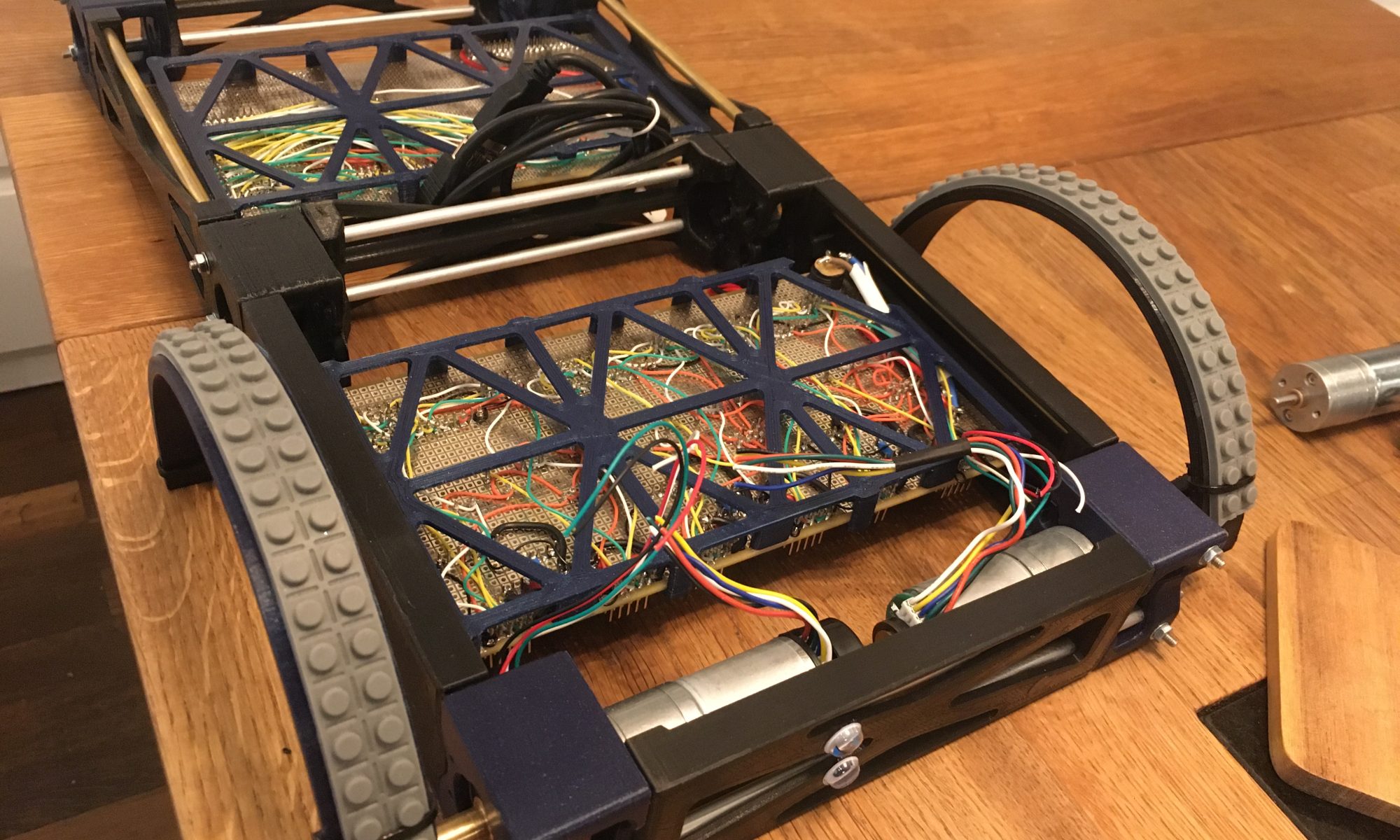
Time to add the full det of 6 legs, so i need a new board to mount the motor drivers.
I took the time to draw up a cleaner design and it is looking very promising. So far, I only wired up a single breaker, but all of the power rails are in place which should allow for massive power and clean wiring even when everything is connected.

So the last weeks I have mostly written code. I now have a nice framework with a command parser that can do the basics.
Today, I felt I was ready to start building the remaining four legs so I can try out the full six-legged locomotion. That means that I will need to buy all of the parts so that will be rather expensive….
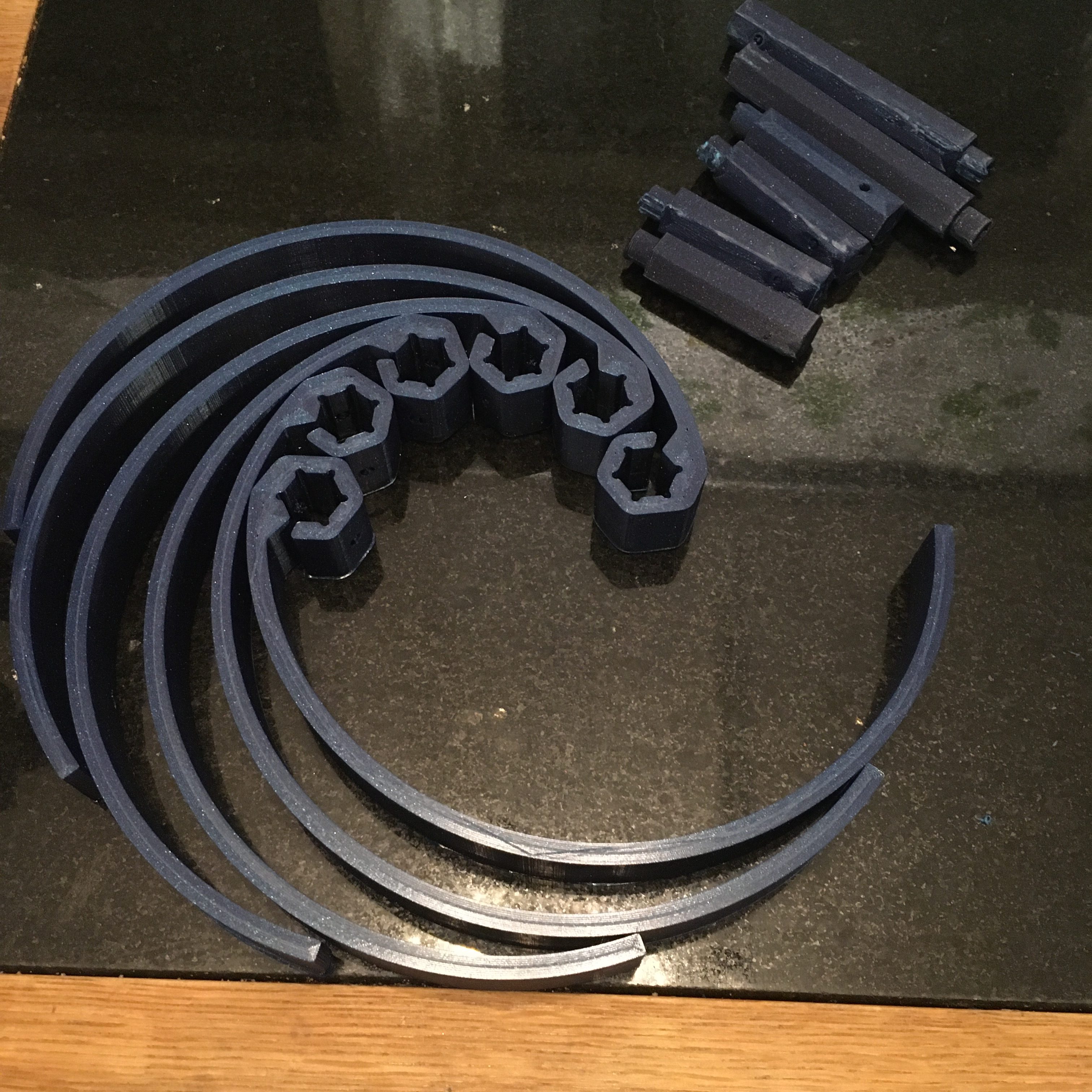
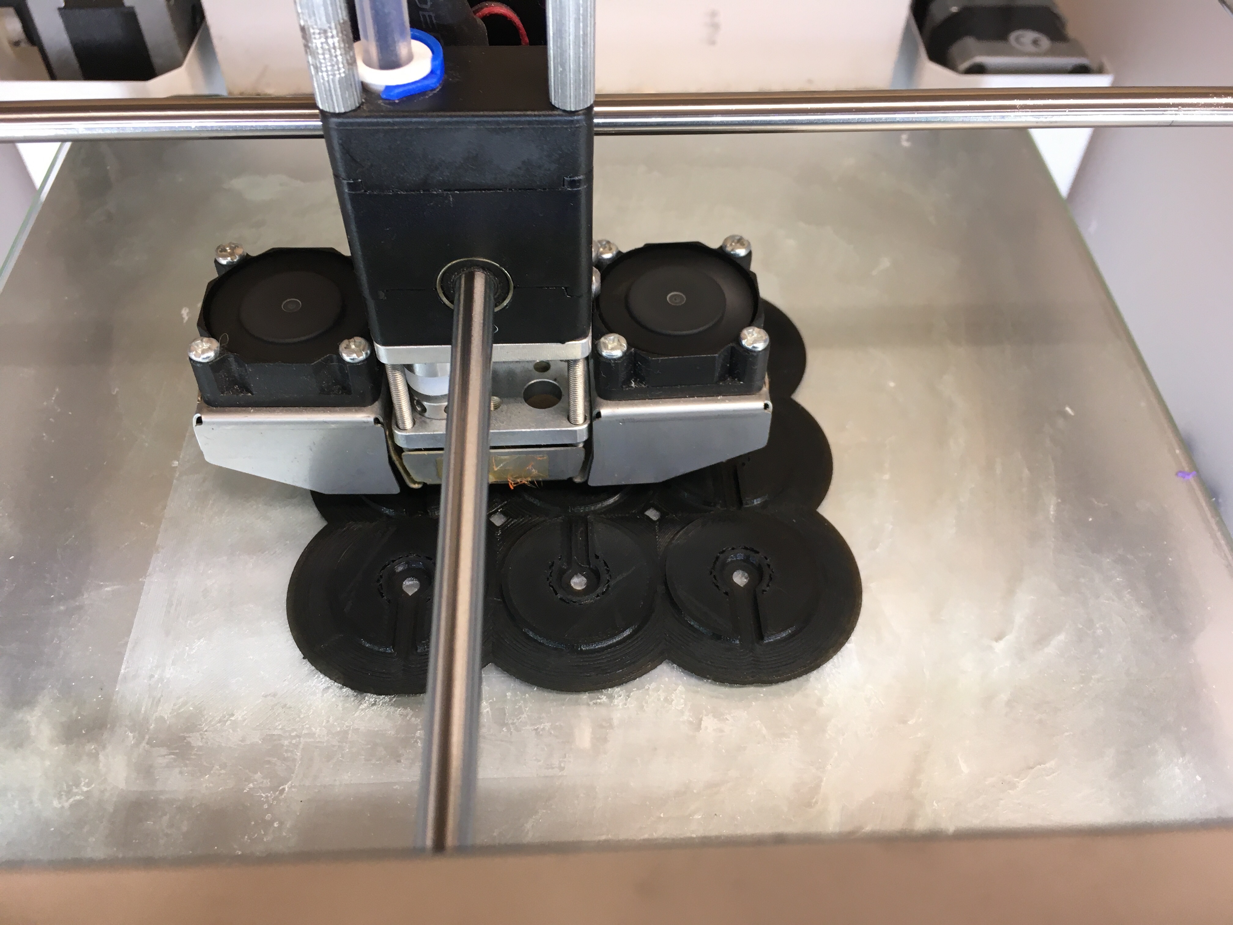
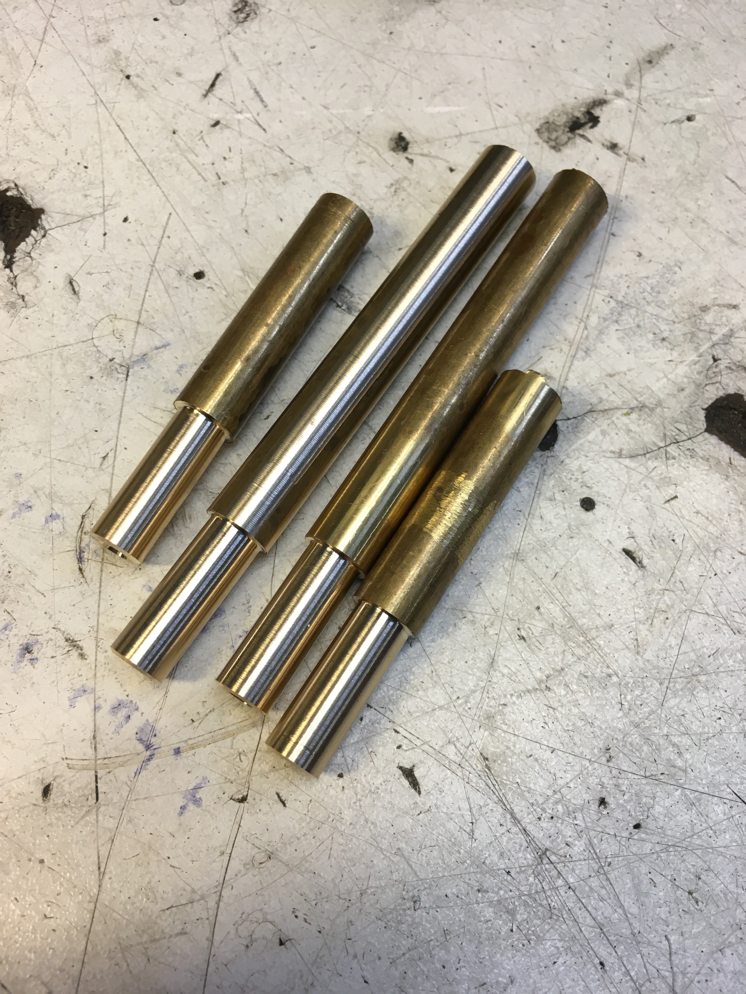
But today, I started with printing out 4 sets of legs and began the machining of the leg axles.
Here we have the 4 legs half-way done
My first attempt at machining a round bar from a square bar. Worked really well. I also learned how to use the motorized sideways motion of the cutter to get perfectly smooth finish. Soo smooth… 😀
And here are the four axels with all of the high-precision parts cut out. The low precision side and the screw holes are left for next time.
So I went to the makerspace today to make sure I could debug any driver electronics issues I might have had with the oscilloscope.
It turns out that I probably did not have any and the motor seems to kick in at about 1.5-1.7V which I think is OK. I get about the same values if I use a power cube as if I use the on-board driver so all is good.
I then went on to debug the regulators and finally I have the software needed to initialize and then start a movement cycle:
I then realize that I really don’t want this thing to start flailing about as soon as it boots. So I rewrote the code to add two-way serial communication and now I can control the state via remote. So it boots up nice and quiet. I can then ask it to slowly home all of the legs and set them to their starting position.
Only then, when all legs are in a good position and the robot is on a flat floor, I can tell it to sltart walking. Very nice 😀
Also, I built a better logger….
So I had a box, but without any cushioning inside, the RHex would simply rattle about and that would not be great. So I planned to get a foam camping mattress and build something from that. Unfortunately, they were all out, so I got some mini foam cussions. It turns out that they did not have nearly the volume that I needed. So the result is super-ugly. But at least it keeps things in place and I can fit a whole lot of material in and around the foam inserts, which is a plus.
Also, I purchased a handle and mounted it. So now I can carry it like a briefcase which is really practical, and on the whole, the outside looks quite elegant.

I guess that I simply need to redo the inside sometime later when I have more contact cement and more foam so I can do a proper job of it.
I had planned to do a bit of programming, but unfortunately, I forgot to check that the power adapter was in fact packed. I had simply checked that it was not in its standard spot, which it was not.
So I spent the rest of the evening doing boring chores on my ToDo-list. But I had a few too many so that it was nice to get them done.