So today, the plan was to start mass-producing frame parts. I need a total of 4 side frames and two front/back frames. The plan was to make half of these just to see that it all fits together.
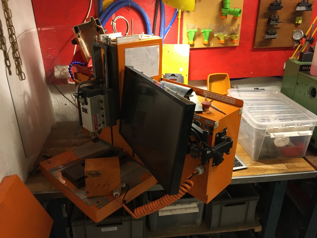
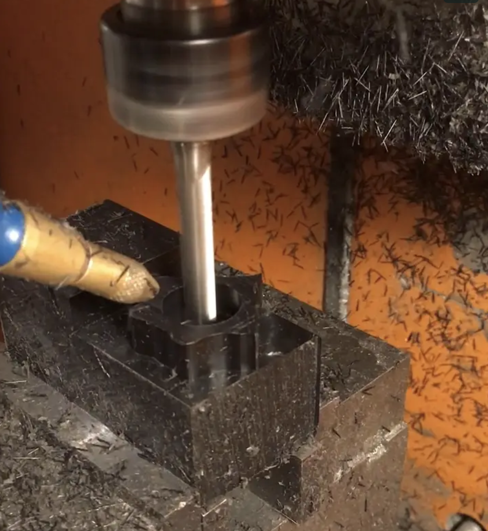
Unfortunately, this is what the CNC machine looks like now. One of the motors has given up and needs to be replaced. New motors are ordered and the machine will be rebuilt, but it will be about 2 weeks.
So I spent a few minutes in the wood-shop and made a frame to mount the motor testbed in and went to work on the regulator. So this is what that looks like now:
So today I knew that I needed to finish one of the motor mounts, complete with bearings and opto-switch and make sure that the entire electro-mechanical setup actually works. And yes, it really does!
[vimeo 374277351 w=640 h=564]
So yeah, the video just looks like a motor starting and stopping, and admittedly, that is what it is. But the rotary encoder on the motor is actually used to rotate the motor exactly 0.8 revolutions via a P-regulator. And now, the opto-switch is also conected so the arduino is detecting every time a full revolution is completed.
So next time I sit down and write serious code, I will have to write an init routine to make sure the motor knows its absolute position as well. But that is just a question of lots of lines of code, so that can wait.
Another thing I realized today is that when you try to miniaturize your design, it actually becomes very small. When most of your dimensions are counted in single digit millimeters, things get delicate. I was really worried that the lathe would not be able to actually produce the rotary disk for the opto-switch. But after a few incidents of the part jumping out of the lathe, I finally managed to be careful enough to get a piece of the right size.
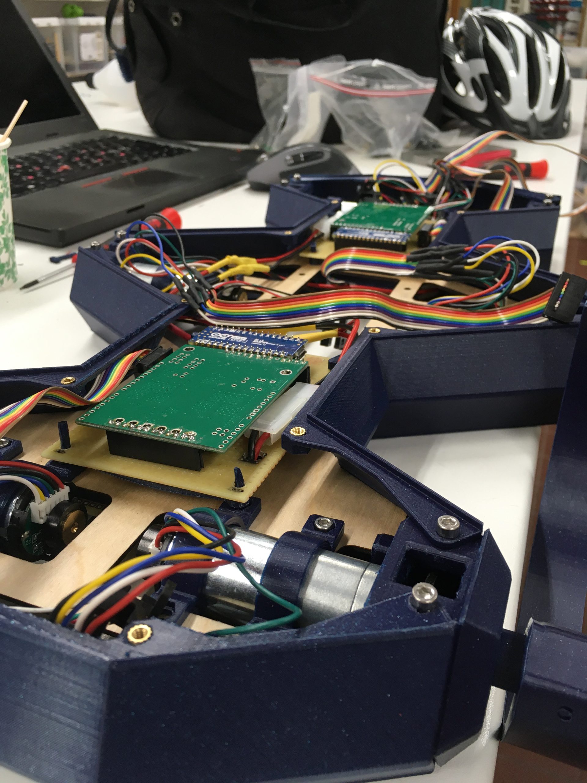
So I will end with a close-up of the motor mounting block. Everything snuggly in place with no wasted space. The rotary disk isn’t fastened in a good way which I need to figure out how to do, but the rest feels solid.
So all of the previous posts were written in one go. So why did I decide to document my process just now?
Well, because I just saw this clip by Bernadett Banner, a costume historian whose video blog I found recently and which very much suits my personality. Yes, historical dressmaking and programming machines to cut metal into pieces that will become a semi-autonomous robot. This is 2019, and I don’t need to limit myself.
Anyways, back to the video I saw. Here it is:
https://www.youtube.com/watch?v=jMGyfkvY06g
I mean, just listen to Cathy Hay’s voice. Did you ever hear a voice so steeped in passion? And it ends with the wonderful quote “Oh, and go do something impossible today”. Yes Bernadette. I will.
Or rather, even if I now realize that this robot project of mine is way harder than I had planned and is going to take a year or two (Or more if I decide to add cameras and teach it to hunt in the night), it is nothing compared to that dress. But impossible was never more than a shade of gray.
So armed with a new design, It was back to the makerspace. Results were mixed to say the least.
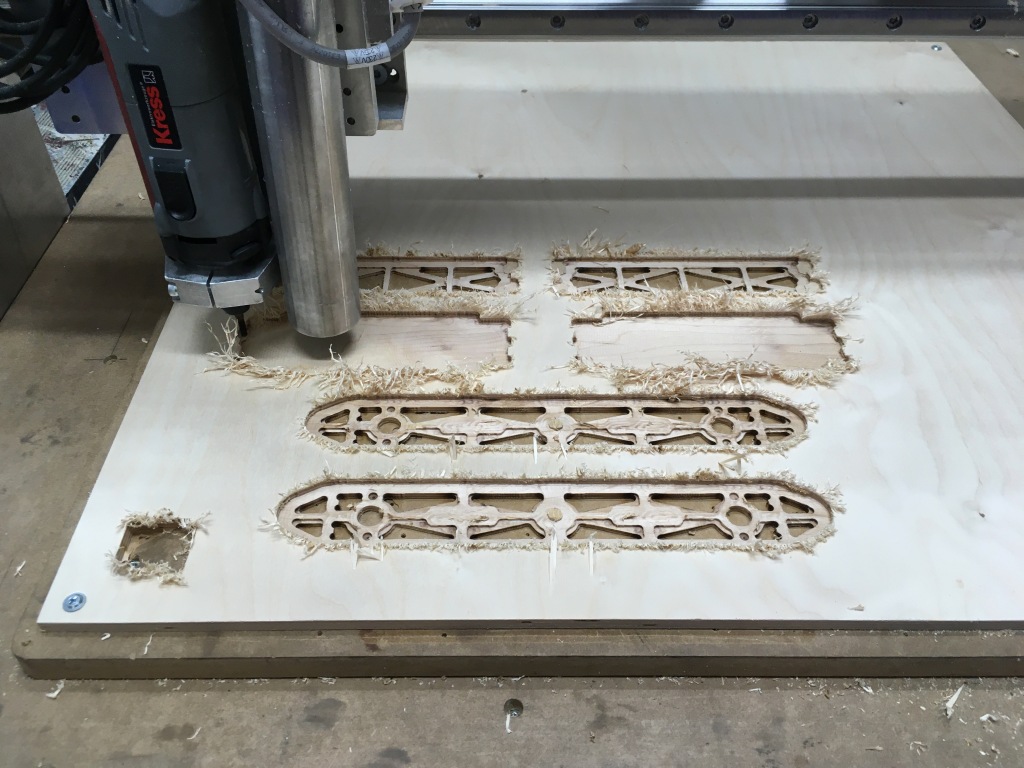
In order to not once more find that I had designed something that could actually not be built, I decided to mill a prototype out of plywood. I had a hunch that is might not work, and boy was I right!
Promising start…
Everything worked out really well until the final finishing passes when then forces from the milling simply lifted the pieces out from their frames and shredded them to splinters.
But no joy….
In the mean time, I tried to mill one of the motor fastening pieces in aluminium. The mister was broken so I used som manual compressed air and alcohol from a squirt bottle. It turns out that that is not nearly as good as having a fine mist of alcohol and air continuously flowing. Twice I had to pause and remove gummy aluminium from the flutes of my mill, but nothing broke at the piece came out as perfectly beautiful as I had hoped. 😀
In order to handle the tolerances, I actually told Fusion that my end mill was 0.1mm smaller than it really was. That worked well as a hack.
I made one mistake, though, and that was forgetting that my ball bearings are 7mm wide and not 8. But fortunately I can fix that by simply removing 1mm off the top of the piece next time.
So my original design has some serious flaws. Going back to the drawing board, I decided to start completely from scratch.
I had two problems. The first was that all of the screws were not as accessible as I needed them to be. The second was that the fram required me to drill holes into the short ends of the front and back walls. This would have required a manual step and I could never get good enough tolerances on that.
Besides, anyone can design a machine that is hard to build. Making a machine that can be manufactured using a minimum of steps and realignments is the challenge. So what I wanted was a design where the motor mountings were the only pieces that required milling from more than 2 sides.
So here is where the magic happens. By using the motor mounts for corner support I think that the design will be completely solid. By adding a few extra interlocking edges as well the screws will not be the only thing keeping the pieces together meaning absolutely nothing should move.
Speaking of movement the side walls should be able to take a load of 25kg without buckling. Aluminium really is a fantastically strong and light material. I see why they build aeroplanes from it. We are after all talking about a structure mostly made from bars that are at most 4mm thick in either direction, most are 2mm thick in at least one direction.
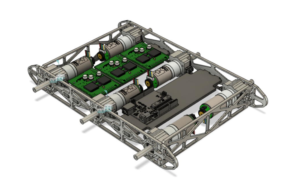
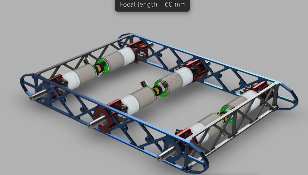
To top it off, here is a rendering of the entire design.
Does not mean that it will work in real life. So I had made sure to leave enough room for the screw-heads needed to assemble the piece. I also had a plan how to be able to reach with tools to be able to actually fasten the screws. All except two…
So I thought I had this milling thing under control…. Not so much. Today everything went wrong.
First I forgot that my stock aluminium piece I was using today was 10mm wider than I have modeled it in Fusion. Que my 4mm endmill digging in with full engagement into the piece instead of shaving off about 1mm at the time from the edges and promptly breaking off.
Went to the shelf of endmills to purchase and found that there is one last 4mm carbide endmill. Mounting in in the machine I slip with the wrenches. That was apparently enough to break the brittle carbide mill clean off.
Went back another time and found another end-mill of a different kind. Mounted it and started. Apparently it is true that end-mills for steel don’t work for aluminium. After a promising start I suddenly hear a snap. And that, my friends, was mill number 3 for the night.
So having wasted most of an evening and some 300sek in broken end-mills I finally went back and milled the piece out with my trusty 8mm endmill that worked so well the week before. The fine detail was lost of course, but at least I got something that looked sort of like my CAD model.
The end-result, two pieces that at least fit together. Could have been worse.
So the Delrin experiment went well! My parts were so thin and Delrin so soft that the pieces got deformed by the vice, but over-all it worked as expected. Time to graduate to Aluminium!
What do you know? A beauty, isn’t it?
Unfortunately, the tolerances were off and the bearing didn’t fit the first time, but that was an easy fix.
Also, I milled two pieces, but learned about peck drilling the hard way. If you try to drill a 2.5mm hole 25mm deep in one go you break your drill…. So now I know. For those who do not know, peck drilling means that you drill a few mm at the time and then pull the drill out to clear out all of the removed material and reapply alchohol mist for lubrication before going down again.
I chose Delrin to get started since if is such a forgiving material. It is oily and does not really require any lubrication. It is soft enough that it will not break my expensive end-mills.
So to build a robot, you need to design a robot. Since RHex was designed by universities (Using military money, of course), you can actually find documentation.. Not great documentation, but still: https://kodlab.seas.upenn.edu/uploads/Main/xrhextechreport.pdf
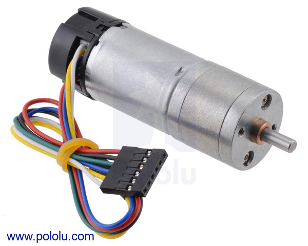
So the original weighs in at something like 10kg and cost like a small car. I decided to aim for a 2.5kg machine. So what sort of motor would I need? Top-of-the line brushless DC motors are out of my budget range, but six of these solid little ones would give me a pretty good kick. This would give me about 10kg (98N) of max upward force. For a 2.5kg robot that leads to a vertical acceleration of about 3g when all legs are pushing at the same time.
Below is the design for the metal frame and the motors in place. The red little pieces fit a ball bearing for stability and an optobreaker to be able to calibrate absolute position of the legs. The space between the motors should fit the DC motor drivers, an Arduino Mega and enough batteries to power the entire thing.