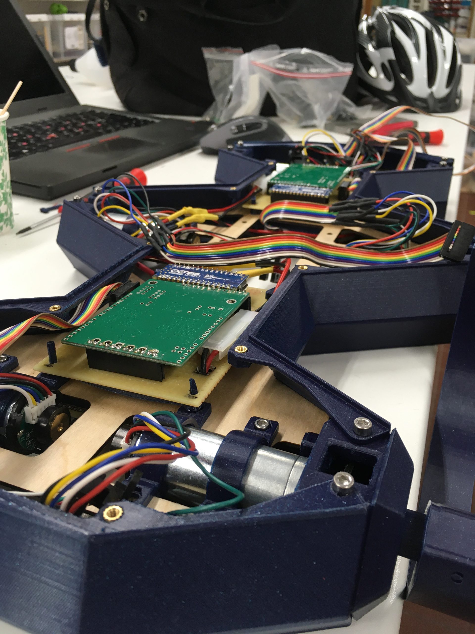
Yeah, so I had some setbacks. When putting it all together, I noticed that 3 of the legs moved nicely, but the other three did not move well at all and I could see the plastic flex as the motors turned.
I had clearly made one of the simple beginner mistakes. I had designed a stiff design that required tight tolerances, without having the manufacturing techniques to get tight tolerances. The holes in the leg axels are simply drilled and that does not give me a round and precise enough hole for the axels to be perfectly colinear with the shaft. Then I tighten the set screw and I get a stiff and crooked machine. Not good at all.
So back to the shop for some experimentation. My first idea was to drill a small 2mm hole in the motor shafts and put a pin through there. That pin could then have gone through the setscrew holes in the axel externders. That would ave probably worked really well, except for the fact that the moror shafts are cearly made out of a super hard metal, so my brand new HSS drill only started smoking, made the wrong kind of noise and then snapped.
What do do?
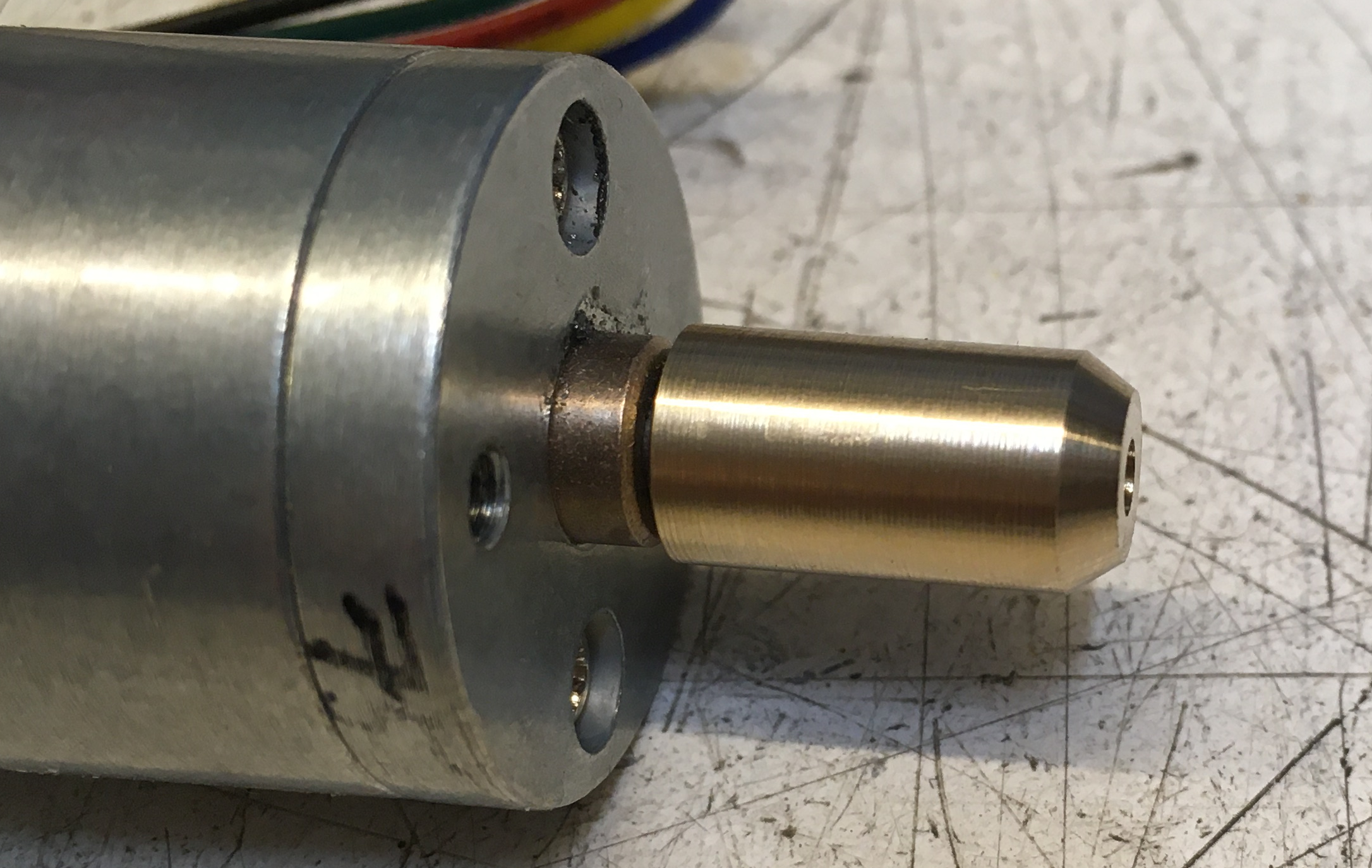
Well, back to design. After some thinking about mixing metal and plastig to get the stiffness I needed to grip the D-shaft of the motors, but then use plastic to get some flexibility. After some back and forth, here is where I landed. A brass collar around the motor shaft. A rather hefty plastic axel. And a m3x20 screw to bind it all together. A key in the brass collar and plastic axel should give some additional grip as the motor spins.
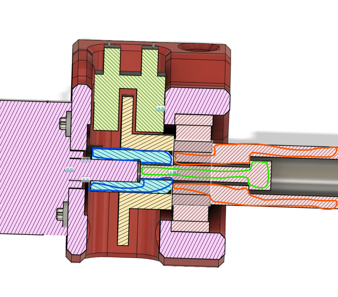
Here is the collar right out of the lathe. Stopscrew holes and the key for the axel are not done here. But I did those right after taking the picture.