Sewing break

So a wedding is coming up. Time to dust off the old sewing skills and take a level in sewing.

A few years ago, I bought the most beautiful blue silk taffeta in Bangalore in order to make a proper evening gown at the next proper occasion. It took a while, but the occasion is now here. 😀

First step was drafting a pattern. After having assisted the manikin to the proper dimensions, I went back to my old trusty method of simply wrapping the manikin in newspaper and painters tape. Then I drew the seam lines on it and cut the paper mold into patterns pieces.

For this project, I had also invested in proper pattern paper with fiber in it so I could see together the final pattern pieces and check that it all fit. It did not so I had to adjust the pattern and then readjust the manikin to fit into the adjuster pattern. This is agile sewing at its best!

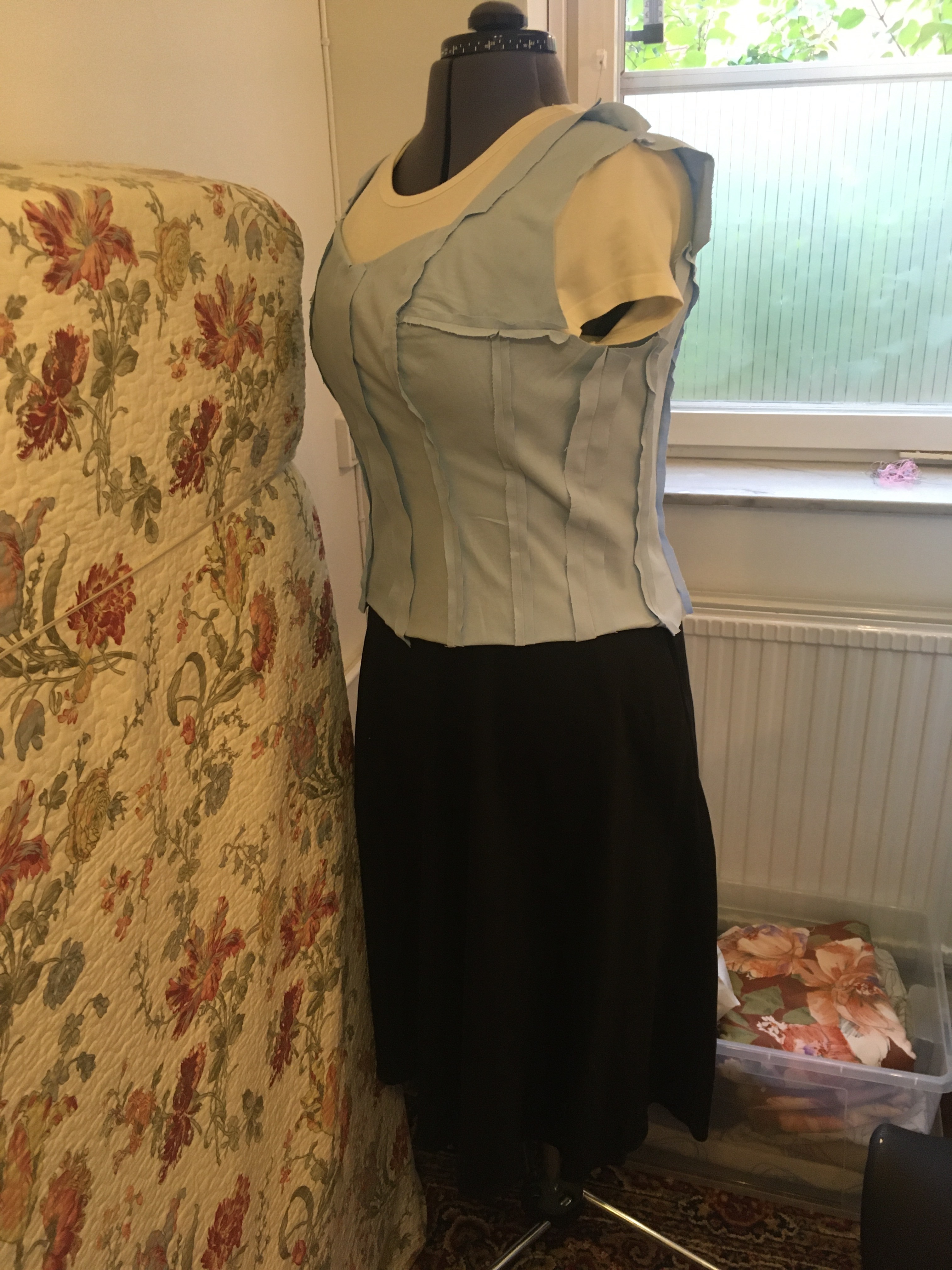
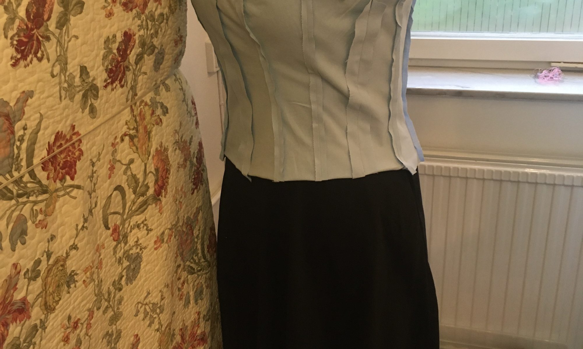
Here we see the inner lining sewn and pressed. I chose to do what I think is the “proper” way. That means cutting the pattern pieces with a wide seam allowance, sewing the pieces together and only then trimming down the allowance to slightly less than one cm and pressing properly.

This method, together with the fact that I chose to make a 7-piece pattern meant that I progressed at maybe a quarter of the speed I am used to. But the result is also way better than what I usually get. So totally worth it!

Oh yeah, the black skirt is an off-the-internet 50s skirt that had the perfect shape and length. So I will simply copy that one for the dress skirt. I will use twice the panels, though to get a chevron look to match the bodice (Yeah, I am getting to that. Patience…)

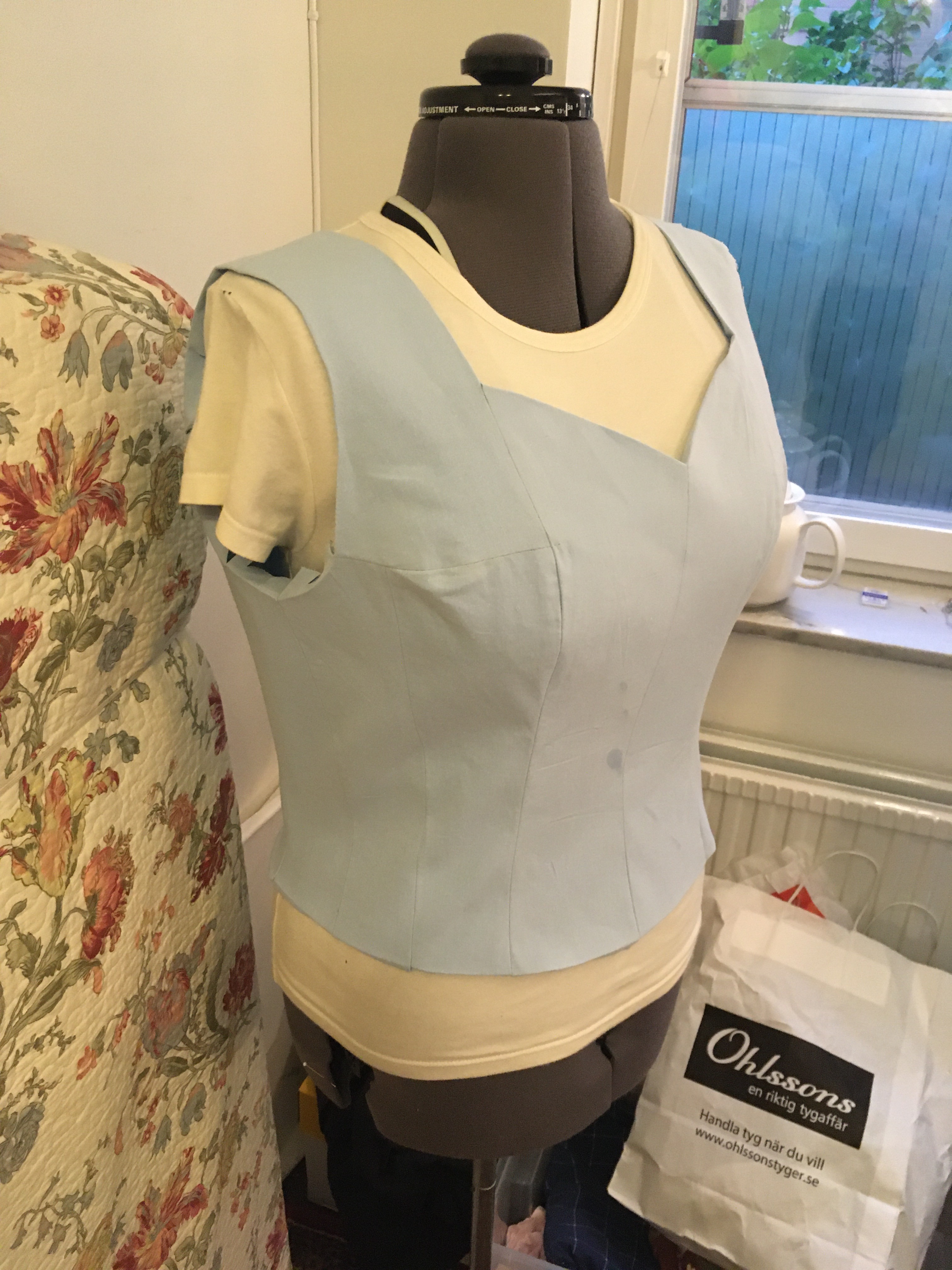
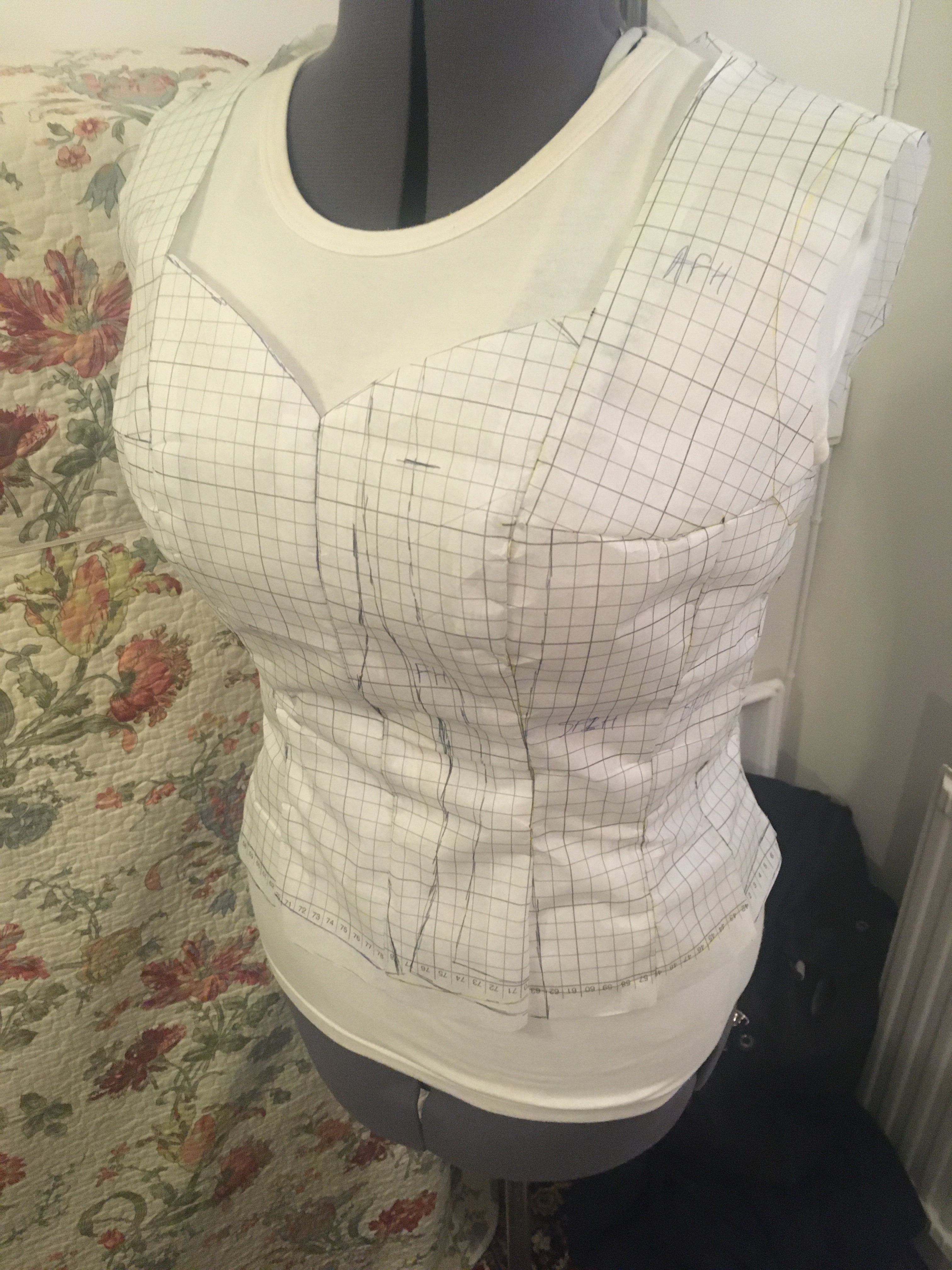
Here is the second of the inner layers. This one has been stiffened with vlieseline. This will be the shaped shell in which I will drape strips of the blue silk. Then the idea is to put the bodice you saw above as lining on the inside for comfort.

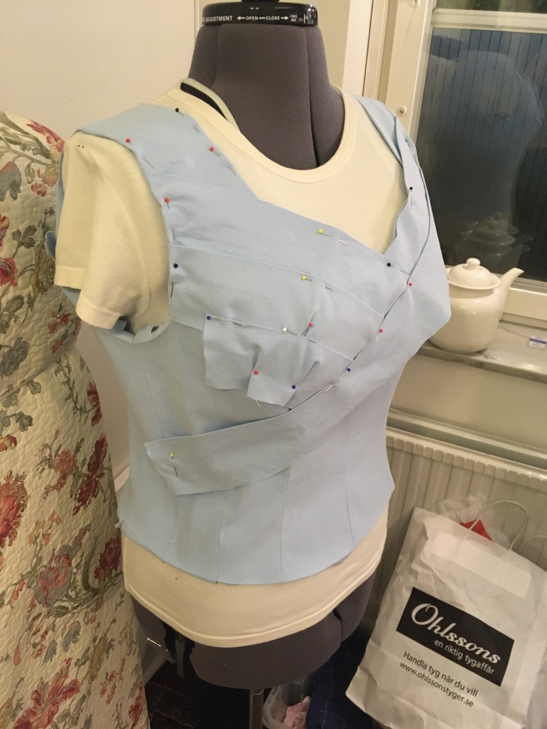
And here we finally see a hint of where I am going with this. The diagonal bands are prototypes and will be made from the blue silk in the final version. These are cut straight on the grain, and as you can see they fold around the cup of the bust. So tomorrow I will try to cut some ribbons on the bias and see if that is enough to get the curve I need.

All wired up, and the case is done

So all three driver boards are now completely wired and tested for dual motor control. One Arduino gave up and let out the magic smoke, for no apparent reason. Lucklily, I had bought a spare right from the start, so that was no issue.

I also finished the foam inlay so the robot is now supported from all sides, lid included. But I also cut out all of the foam that wasn’t doing any work so I have some space for other stuff that I want to pack along.

The driver boards are not fixed properly as I am missing a few screws of the proper length. These are ordered and should appear soon. I have also ordered an angled USB cable to be able to program the Arduinos even then they are mounted in the proper position. Until then, I have placed one of the driver boards where the batteries will go in the future to get access to the USB port.

With this, the list of things to do has shrunk down rather drastically:

  • Add some rubber grip to the legs.
  • Wire up the I2C bus and mount a controller Raspberry Pi (Need to order that as well).
  • Make the leg-controller code more robust.
  • Fine-tune the leg movement regulators to give even smoother movement.
  • Program the gait-controll
  • Done!

Big push at the makerspace

So this week I had scheduled a serious push to really make some progress and I have been to the space every day of the week so far. Yesterday, unfortunately, I got a bit of a cold, so it looks like I will have to cut things short and work from home tomorrow. But I think I have all of the pieces that I needed from there, anyways.

The first success of the week was when I, after a few failed attempts that were all my fault for not ensuring there was proper support, managed to dial in how to print the front cover. As you can see in the image, the only supports were along the purely flat edges. All the rest worked as simple overhangs (They are about 70 degrees). I finally had to draw a super-detailed support blocker which completely determined where there was to be support and where there was not to be support. But once I admitted that this had to be done, the results were spectacular.

The next big thing I did was create two more driver boards. After having miscounted a pin on the first one which led to the motor not running at all, the rest went almost without issue. Here is a work-in-progress image of one of the driver boards. Can you spot the stupid error on this one?

If you look closely, you can see that the small bank of 4 resistors are wired together on both ends. Yeah, sometimes you wire resistors in parallel, but this was not a case like that. That was a lesson in allways controll-measuring your connectors before running them. Fortunately, there was no damage.

A third major component that was missing was the additional covers and leg join chassis. The covers printed perfectly the first time. The leg joints, though. There are pretty solid and rather complex, so they take forever to print. First two Bowden tubes fell out which stopped the prints. Then some really wierd issue happened, twice, where the printer simply fed back the filament and then continued printing as if all was fine. The theory is that the SD card was getting a bit old.

Here you see the last half-completed print. It is something like 90% done. Forunately, Erifor helped me out and showed me how to restart the print, and he tells me that the final pieces are now successfully printed. Will pick them up tomorrow.

Oh, and he cut out another cover with the laser for me, so I owe him twice.

With that, I could assemble the whole thing. You can for example see the pins that I drew and printed to attach the driver cards. I will replace those with long screws, but I didn’t have any.

Also, you can see the power cabling if you look carefully. If I connect all three driver boards, then they reset right after start, so I think I will need a more powerful power adapter. I will have to measure the voltage drop as I power the machine and see if that is the real issue here. But for now I can still power up with two driver boards and that is enough.

Oh, and I also created the inlays for the case. No picture of that right now, so that will have to come next time, if I remember.