A Steam Engine
With almost all the last fixes on the apartment done, I felt that I needed a new project to pick up. Something that in no way was practical and had a deadline, but just for the pure joy of doing it.
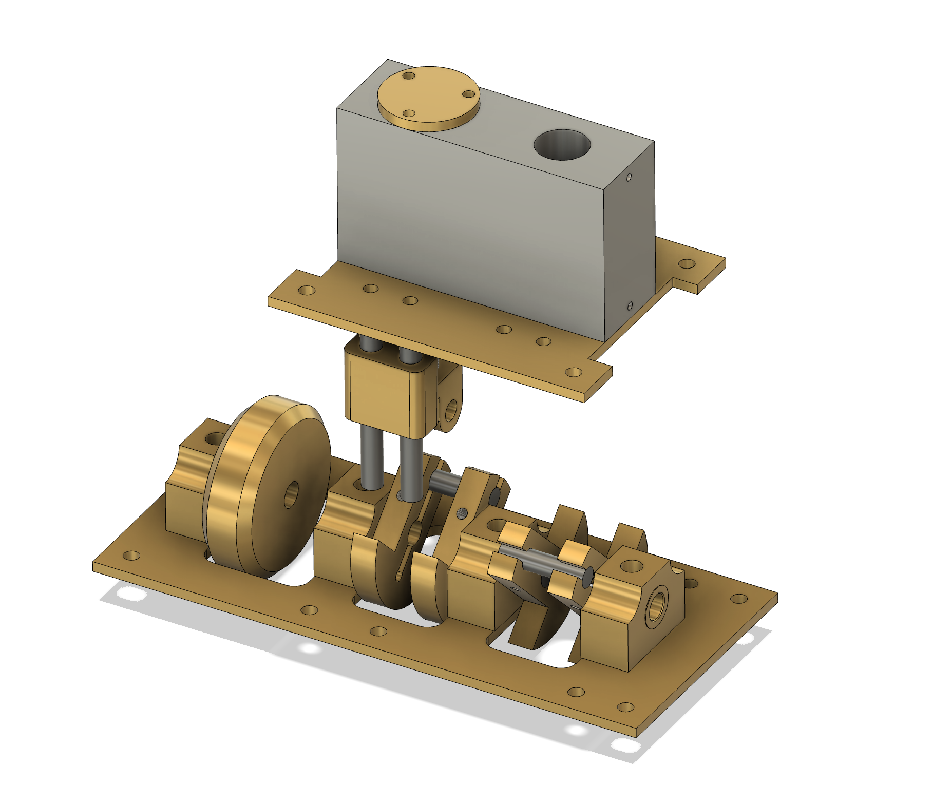
I decided to try to build a steam engine from scratch. I spent all of that time in the hex project learning CNC, but then in the end I never really used it. And if I am to get some credibility as a hobbyist mechanical engineer, a steam engine is the perfect portfolio piece. Nothing speaks old-school engineering quite as much as a steam engine.