Z-axis done and Y axis parts all done

So I really love manual machining! If the mill and lathe had only had digital readouts I would probably have used those instead.

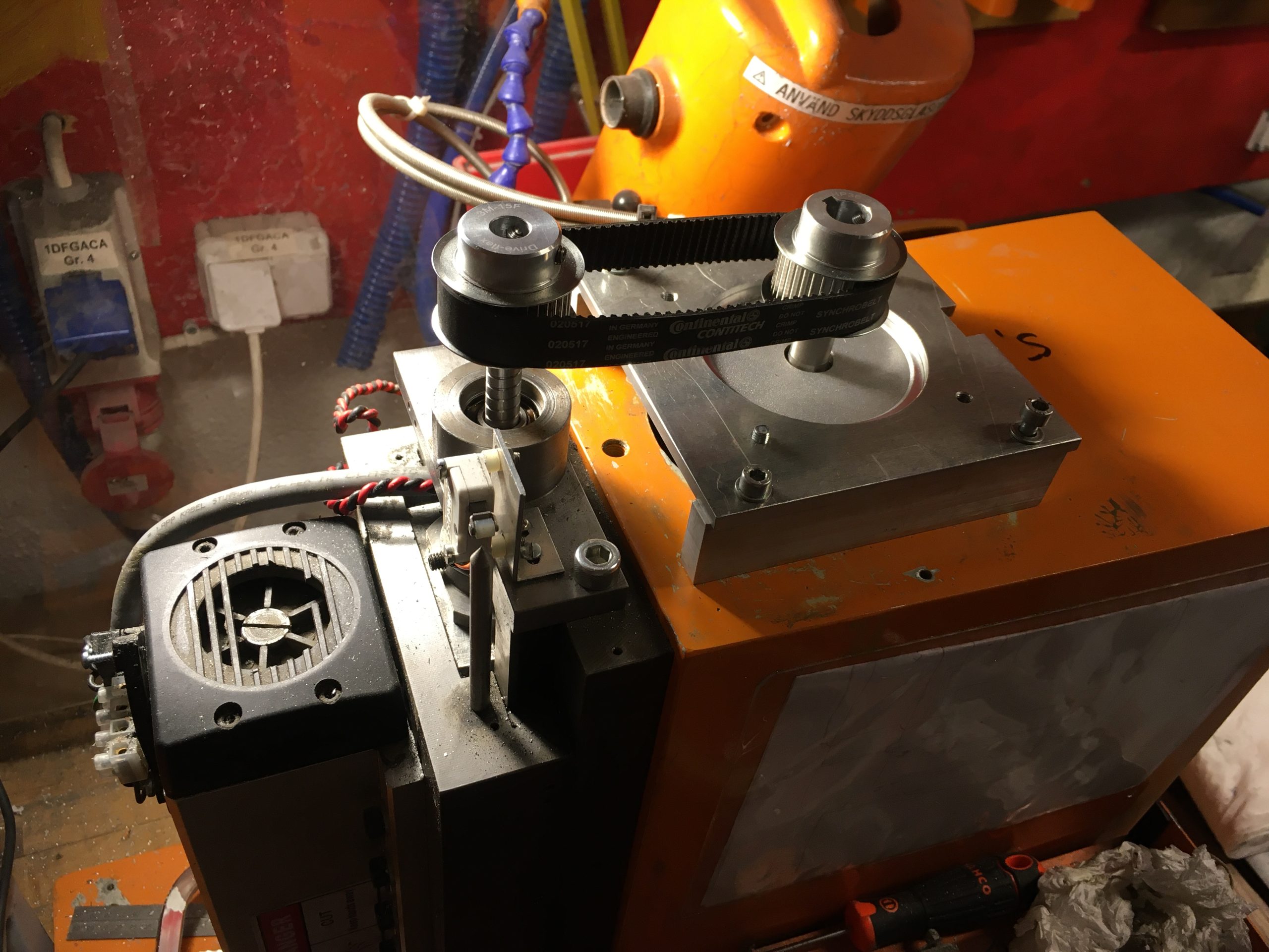
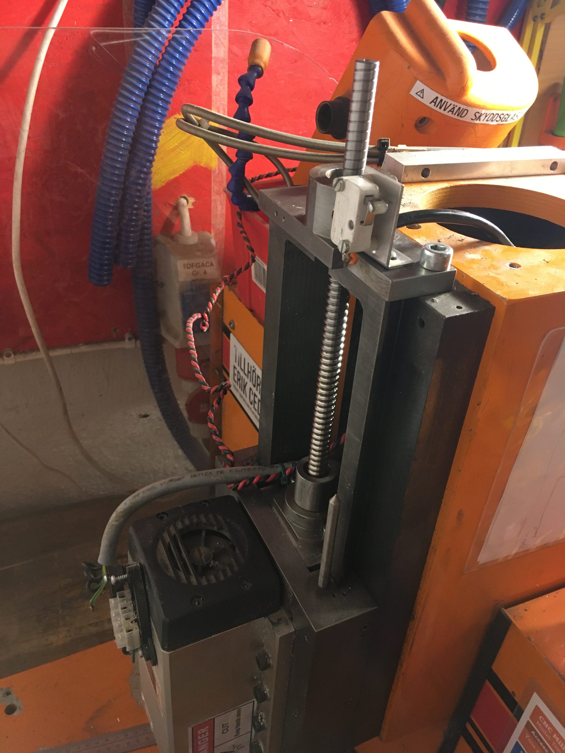
Either way. Today the Z-axis was completed. The drive belt is tight and the cables are all nice and tidy thanks to Magnus.

Next step is the Y axis. Since the new motors have longer axels, a 25mm thick spacer was needed.

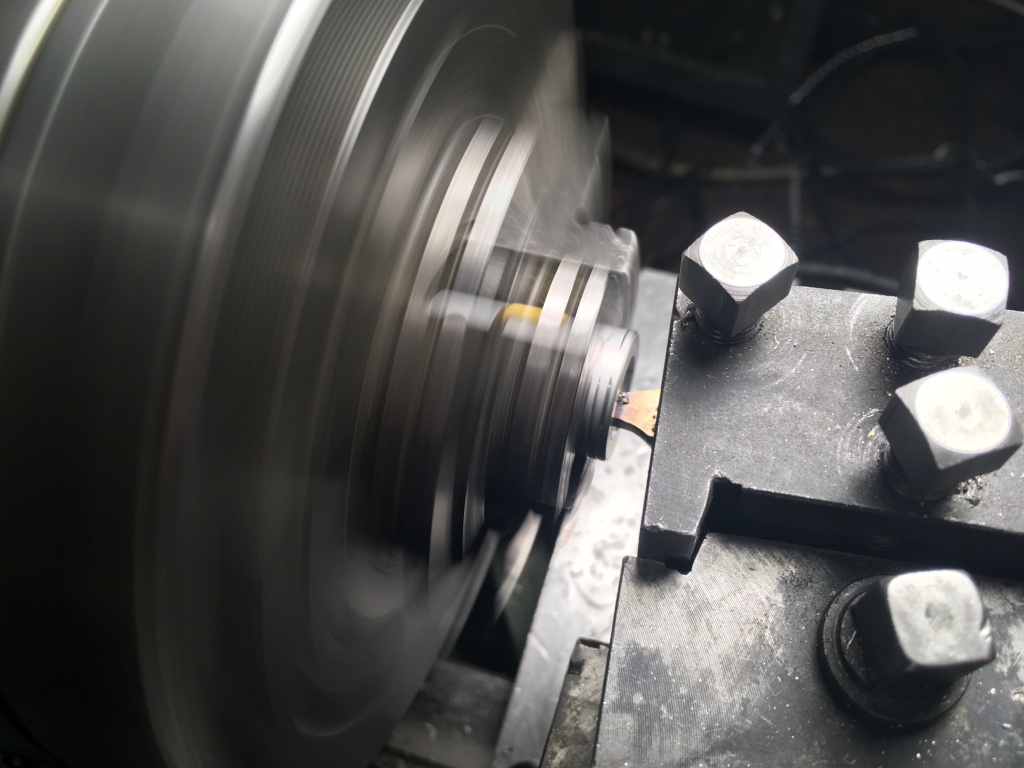
Since the motor and bearing house both have circular centering edges, I decided to add matching edges to my spacer. Putting round concentric holes I a square piece turns out to be really easy if you start with a center hole big enough for the lathe chuck to grip it from the inside.

So first make a hole.

Then make a bigger hole.

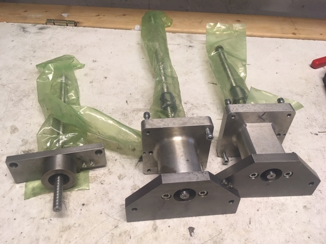
Finally, after learning even more about how to not shape turning bits, here are all of the pieces.

Final step was to drill and tap the bearing house holes to make them M6 threads. Turns out that when you are tired, you may forget that an M6 thread cannot be made in a 6mm hole….

Either way, my bolts are unreasonably long so I can use nuts instead. No harm no foul.

Here are all the pieces. Now just need to cut a hole in the chassis to fit the longer assembly and then mount all pieces together.

Z-axis completion (Almost)

So the goal for today was to finish the Z-axis. I almost succeeded.

The first step was to turn a hollow axel that I could use to change direction of the Z-axis ball screw nut. These nuts contain a large number of tiny metal balls that are tightly fit between the ball screw nut and the ball screw itself. If you unscrew the nut, all of the balls fall out, and I doubt putting them back is is even doable without proper tools or whatever they use to assemble these in the factory.

So about an hour later, after having learned a lot about tolerances and surface finish when turning Delrin, I finally had my little tool and could unscrew the nut onto it. This was the easy part….. The tape is there to stop the nut from slipping off.

A deep breath later, I put tape on the other end and removed the original tape to be able to roll the nut back onto the screw. I didn’t even have to fiddle. The tolerances on these things are amazing!

So here it is, the Z-axis ball screw with all parts in the right order and direction.

The next thing to fix for the Z-axis was opening up the hole in the chassis for the new larger motor to fit. The chassis is something like 10mm thing aluminium. Aluminium is a soft metal. How hard can it be?

Two hours later, I can say that cutting though aluminium is horrible. Everything we learn about aliminium when milling it is also true for cutting it. And none of the tools in the makerspace were really doing the job. Finally, I realized I could drill holes and cut between them. Finishng the first corner was a true victory and worthy of a photo:

And just towards the end, I saw that we had a battery drivern electric angle-grinder with a proper cutting disk. Has I used it, the entire cutting would probably have taken 15 minutes instead. Either way, now there is a large ugly square hole in the top of the chassis and the motor and all pieces fit 😀

So in summary, Z-axis is amost complete. The belt you see above is a bit loose, so I need to make the motor mount adjustable. Also, I noticed that the new motors have 6mm mounting holes while the old mechanics have what look like m5 screw holes, so I will probably drill those holes out as well and rethread them to M6 holes while I am at it.

Vad är nästa steg?

Z-axelns homing switch

Det ser ut som att det är så här den skall sitta, men då når inte pinnen till den innan kulleden går i taket.

Z-motorns hål

Vad är bästa sättat att göra hålet i aluminiumchassit stort nog för motorn att gå ner? Helst skulle jag använda en liten handhållen sticksåg med metallblad. Finns det en bättre metod?

Y-axelns montering i chassit?

Jag kommer behöva montera isär och ihop både X och Y-axlarnas lagerhus för axlarna pekar ut ur fel ända inser jag nu. För åt minstonne Y-axeln så behöver jag dessutom montera isär den helt och hållet en gång till för att alls kunna gå in den.

För jag antar att det är helt orimligt att skruva av skruven på kulaxeln? Då lär alla små kulor rulla ut och vara helt omöjliga att sätta in igen?

Jag är lite orolig att axeln kommer vara svår att trä genom alla hål frå utsidan även om jag tar bort alla lager, men vi får hoppas på det bästa där.

Inga kullager för X/Y-axlarna?

Är det så att det inte är några kullager mellan de tunga metalblocken som utgör själva X/Y-axlarna? Man bara smörjer och spänner åt med skruvarna så att det blir lagom lite glapp?

Completing the driveshafts

Todays task was to complete the driveshafts, ensuring they are completely stiff as well as adapt the axeljoints to fit on the motors. This turned out to be more interesting than planned.

The first step was to test the bearings I made last time and ensure the were properly shimmed and were completely gap free. One of the shafts needed one additional 0.1mm shim. Now they are all three rock solid. The flex in the construction is smaller than the flex in the 10mm thick steel plate that they are attached to.

The second step was to open up the holes in the axel joints to fit on the motor axels. With a bit of careful mounting, that was a piece of cake.

But these motors need to have keyed holes. So I saw this video a while back about the “broach” technique for making non-round holes. Skip to 9:56.

So suddenly I am doing a whole handful of firsts:

  • Grinding a piece of HSS metal into my very first custom tool.
  • Mounting said square tool in a chuck.
  • Actually successfully broaching a key slot in each of the three axel joints.

The result wasn’t particularly pretty because I didn’t grind as much on the tool as I chould have, but for a first ever I am really pleased. I feel that once you have broached a hole with a custome tool, then noone can even call you a newbie again.

Finally all the pieces for a complete driveshaft for an axel. And below we have the Z-axel completely mounted. 😀

The Terco side-project

Seems to be my new main project for the forseeable future. Building a CNC machine is not done in a day, even if all of the parts mostly exist… Also, I have done my first 3d-print but I will need to colect it tomorrow as it did not quite complete before I had to go home.

So today I started with the rebuild proper. A run-though by Eric Cederberg about which parts belonged where, and I got working.

Cutting down the fastening collars to the right width.

Above you see the fastening collars that will attach the ball screws to the bearings. These carry all of the force of the movements, so getting them to exactly the right size for a snug fit in the bearing houses is critical.

To make sure the collars do not start slipping after a few years, we decided the drill through the collar and ball screw and fixate them with a spring steel pin. This was really scary as the ball screws are custom made in Asia meaning they are expensive and delivery times are long. Obviously, we had no spares.

Drilling through expensive ball screw rods…..

Either way, the goal was to get the entire assembly to be about 27mm wide, and I find that the tolerance achieved is perfectly OK. 😀

Allways nice to achieve 0 tolerance

So below we see the status right now. Three ball screws securely fastened in their bearing houses and the most critical part of the build is completed. Note that the Z-axis bearing house is not actually assembled as the other part of the bearing house is stillf astened to the machine.

Final results for today

So that was a good first day. Next steps are:

  1. Drill out the motor holes from the axel joints so they fit our motor axels.
  2. Fasten the axel joints onto the ball screws. This requires disassembling the bearing houses above. When doing that, the shims should be rechecked. I believe that one of the bearing houses perhaps should have 0.1mm less shims and the other 0.1mm more shims to be perfect.
  3. Open up the gap in the Z-axis mount plate on the Terco a bit more as these ball screws seem to be a bit wider than the originals so the Z-axis cannot actually be mounted as it is today.
  4. Start assembly of the Terco.