First successful i2c communication

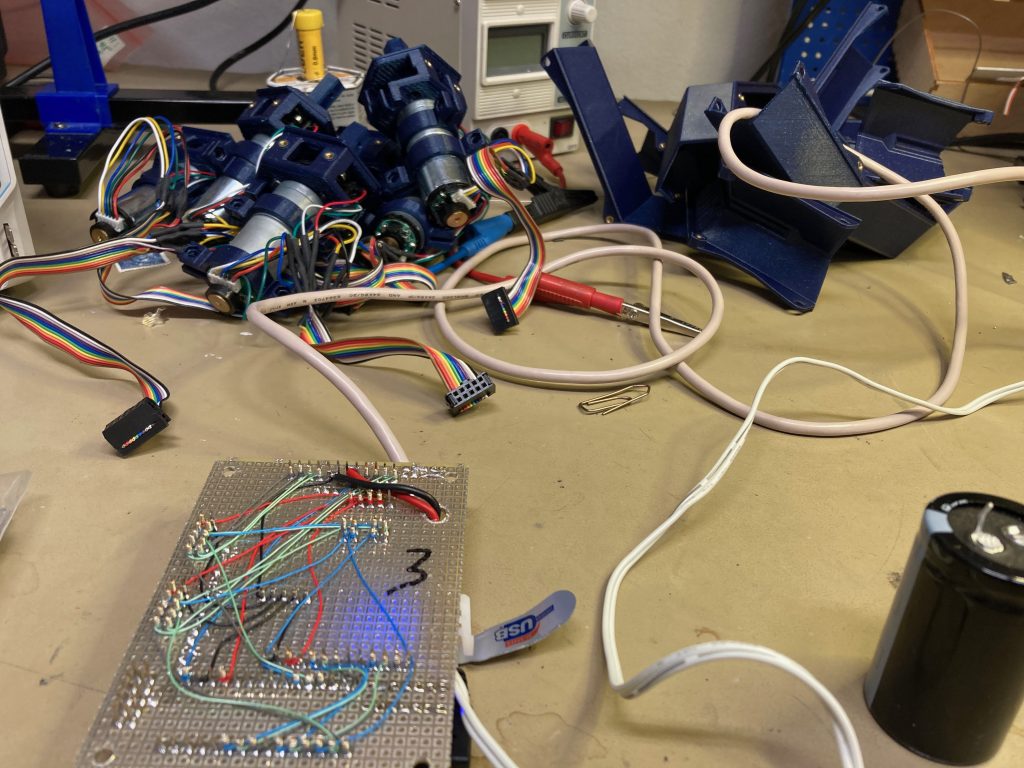
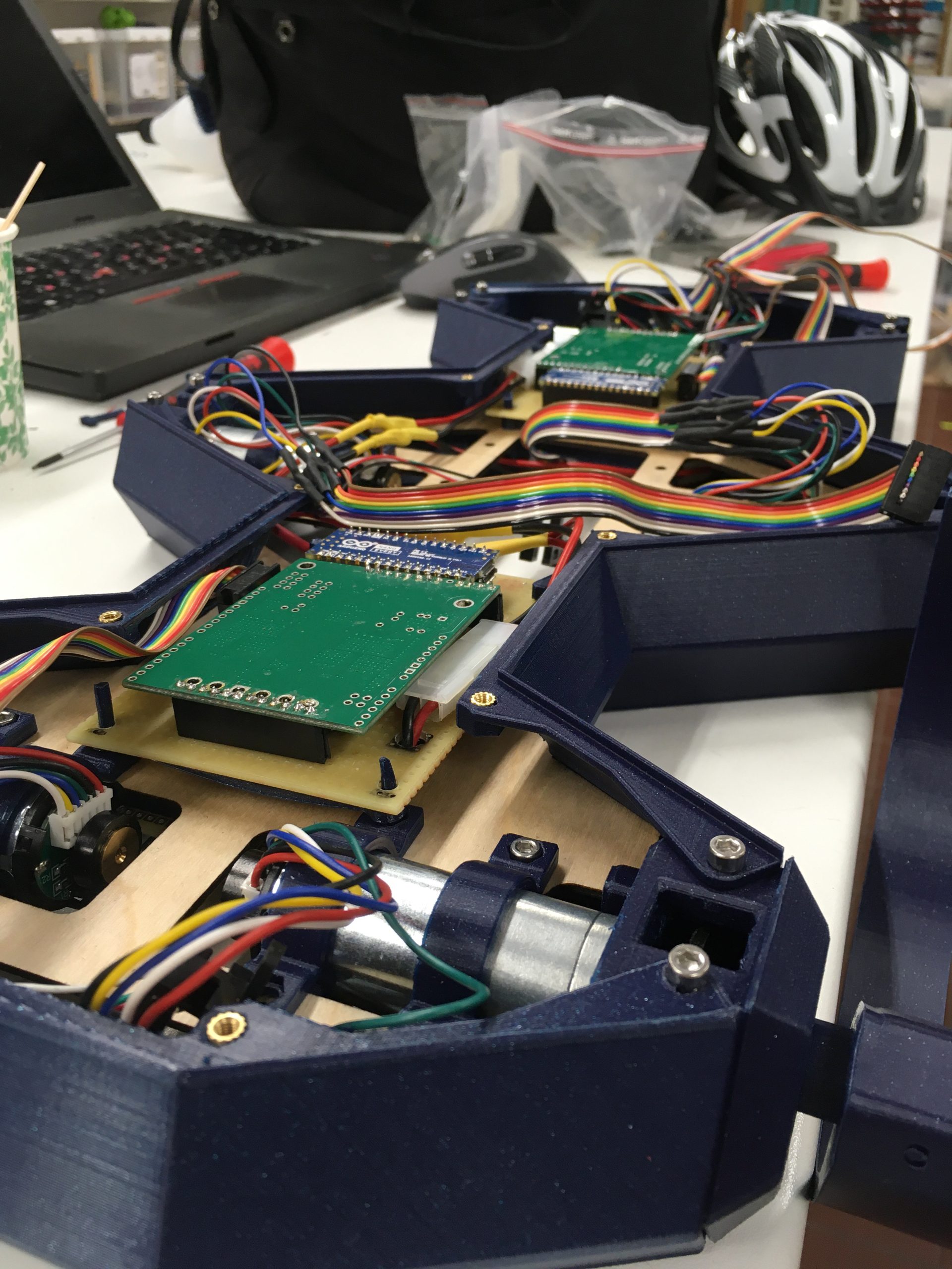
The robot is build with four independent circuit boards. Three of them are driver boards that power and control one leg pair each. Each driver board contains a dual motor driver and one Arduino. The Arduino is programmed with the low-level logic to drive the legs, including a PID, homing encoder support, etc..

However, the way this robot should walk is that the two opposite tripods walk together. So something needs to sync the three driver boards. This is where the controller board comes in. Right now, it only has a single Arduino on it, but I have space for a Raspberry Pi Zero are well for future expansion.

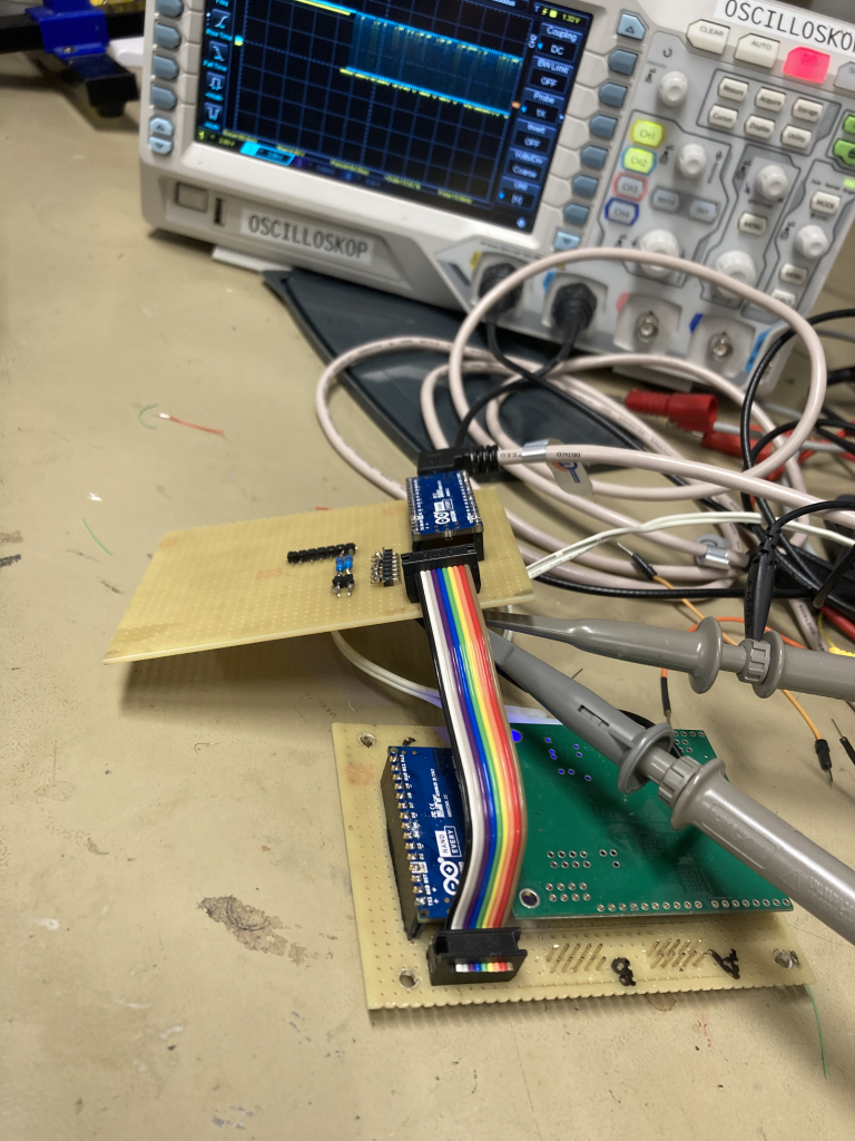
The idea is that this controller board should send step commands to the driver boards via i2c. The first time I tried to get an Arduino to speak i2c, I got wierd results that I did not understand.

So off to the Makerspace to hook up an oscilloscope and see what was actually going on. It turns out that the pull-up resistors really were necessary to get decent signals, and apparently an i2c master should not send data unless the correct slave acknowledges that it is listening.

Below we see the little Arduino calling out all properly to its slave device, but getting no answer so it falls silent….

Some soldering and wiring later, the controller board was ready and I could hook it up to one of the driver boards. Some coding later, and the two boards can now send data between each other. I believe that the oscillosope display says “Hello World!” 😛

First crawl!!!!

Yeah, so it happened.

First I made an improvised fire-proof charging station. I wonder if the people who cast this pot literally almost 100 years ago could have even fantasized about the kind of battery power we have access to today….

So attaching two legs and the battery, I finally managed to get the thing to walk across the floor…… 😀

… Yeah, I might not exactly have paid the royalties for the music in the background….

High-current batteries

I spent most of February and early March rewriting all of the code to have clean structure and complete unit test coverage. Unfortunately, there are only so many screenshots of code that you can show before it gets boring…. But a small contribution map from GitHub will have to suffice.

Now the code is clean and I have a gait commander that can control each leg individually. Unfortunately, I noticed that one leg was not behaving at all. And then my Makerspace lab access expired and it took a few weeks to get it back.

Finally, I could use the oscilloscope to diagnose the problem. It turns out that the detector pins for one leg were connected in the opposite order as compared to what I had assumed. So the encoder homed on every click of the encoder. Not great. But at least, all of the motors and all of the driver boards are now thoroughly tested and there is no electronic noise or any vague digital signals anywhere in the system.

So from now on, I just have to worry about software and mechanics, which is nice.

Testing all motors and all of the driver boards to ensure that all electronic signals are clean and noise free.

Having reconfigured the pins and reassembled all of the pieces, I decided to let the robot try to crawl forward for the very first time. It bravely started taking a first step. And then all of the microcontrollers reset. My assumption is that the power source simply cannot power the motors under any form of load. The power source I use delivers a maximum power of about 12W. But each motor has a stall power of 60W, so I would not be surprised if there is a voltage dip when two motors push off from the ground that causes the controllers to reboot.

Clearly, I cannot continue development if the robot cannot even take a single step with only 2 motors. So I ordered two 7.5V 1Ah LiPo batteries and a charger. Connecting them together gives me around 15V, which is plenty to power the motors. With a max discharge rate of 25C, I will have access to a peak power of around 375W which should be plenty.

Since the system is now powered by more than 12V, I have to do some limitations in the software to not overheat the motors. But they should survive bursts of more than 12V, which is all that we will see as the legs will not spin at max speed continuously.

My weak soldering iron wasn’t too happy about the massive power leads from these batteries, but with some patience I finally had a serial coupling and could connect the power connector that I use.

I haven’t had the opportunity to test this more than to see that the system boots up when powered by this battery, but I have high hopes.