Big push at the makerspace

So this week I had scheduled a serious push to really make some progress and I have been to the space every day of the week so far. Yesterday, unfortunately, I got a bit of a cold, so it looks like I will have to cut things short and work from home tomorrow. But I think I have all of the pieces that I needed from there, anyways.

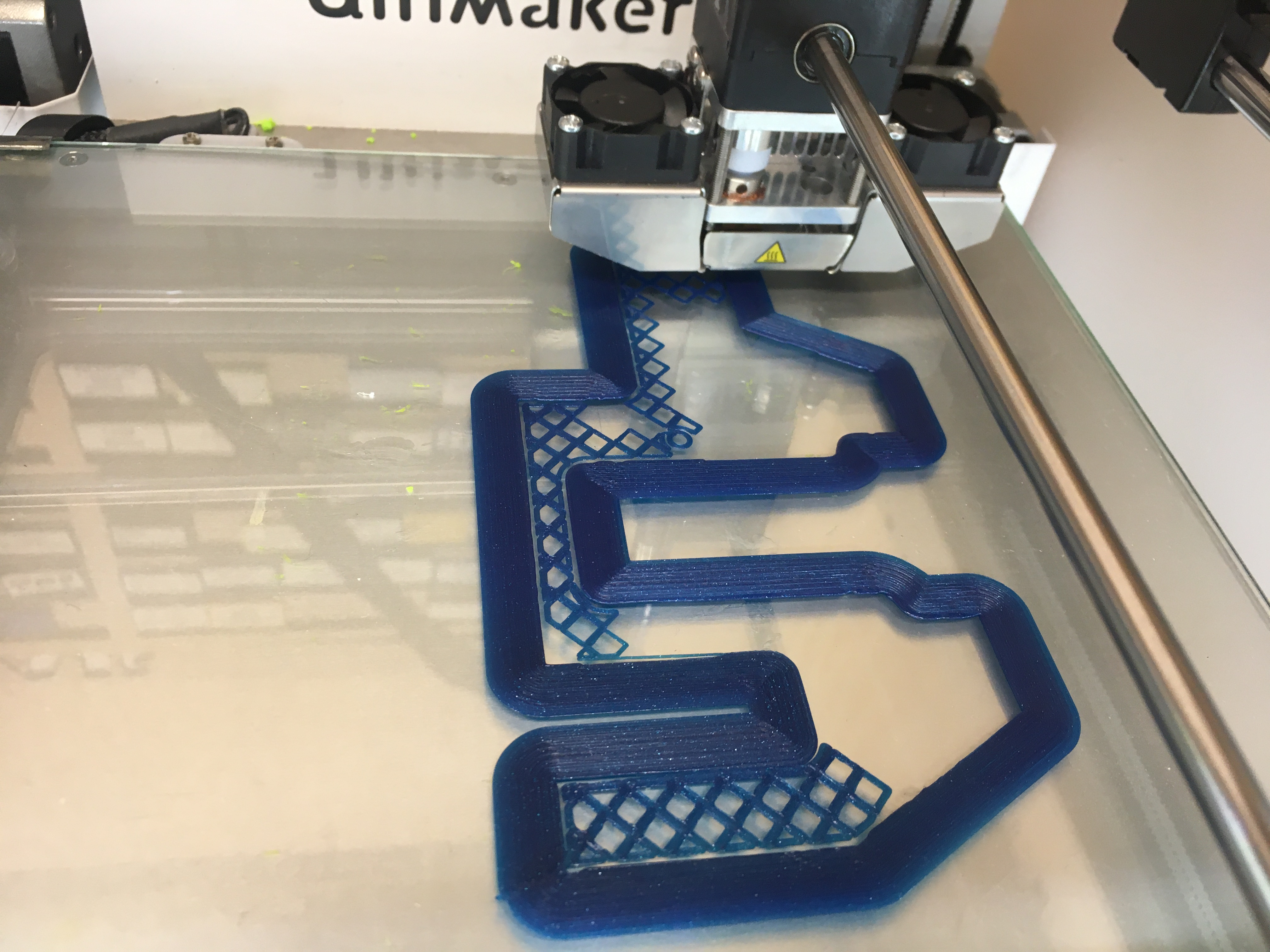
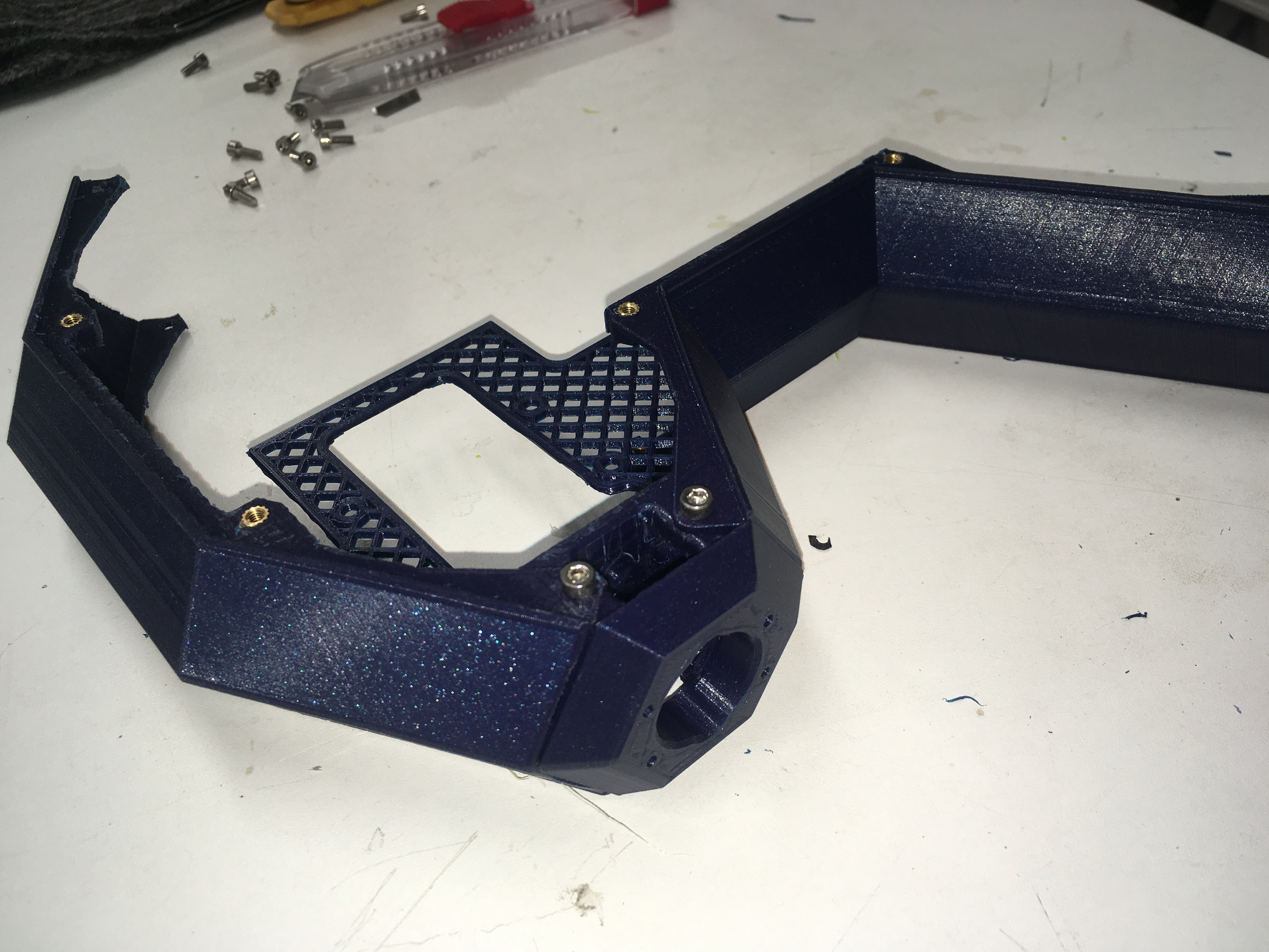
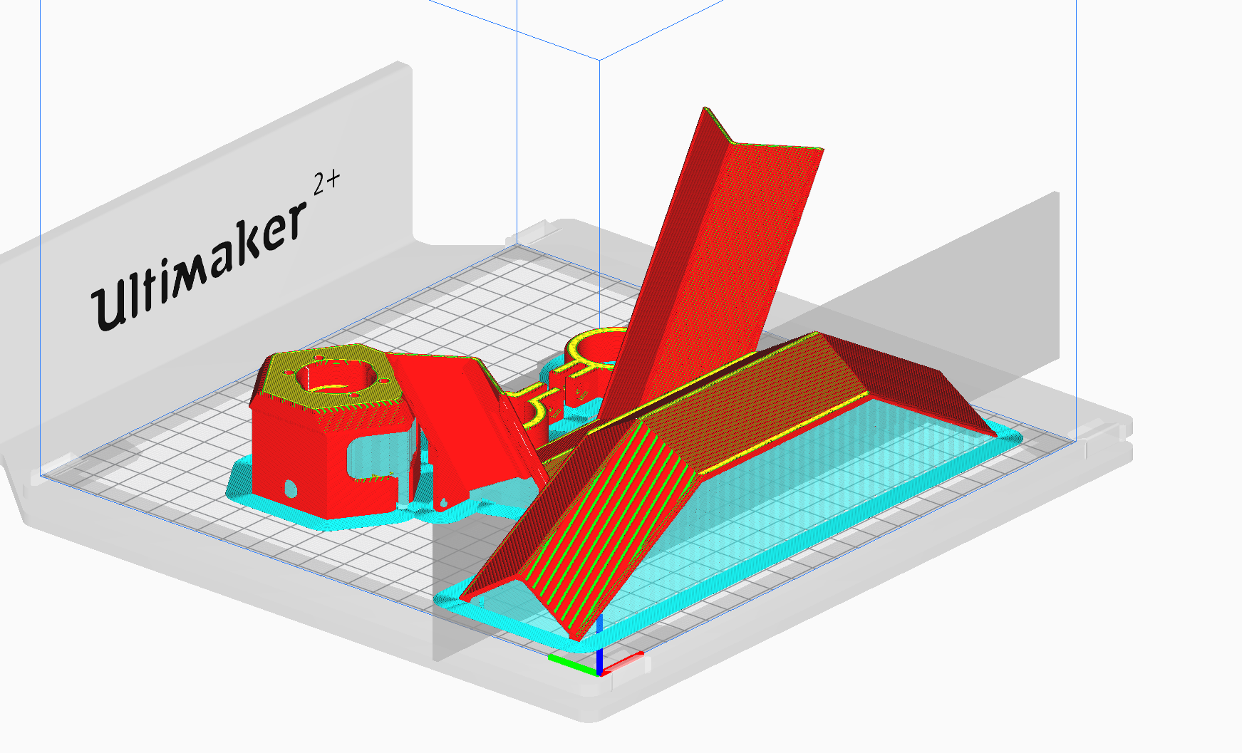
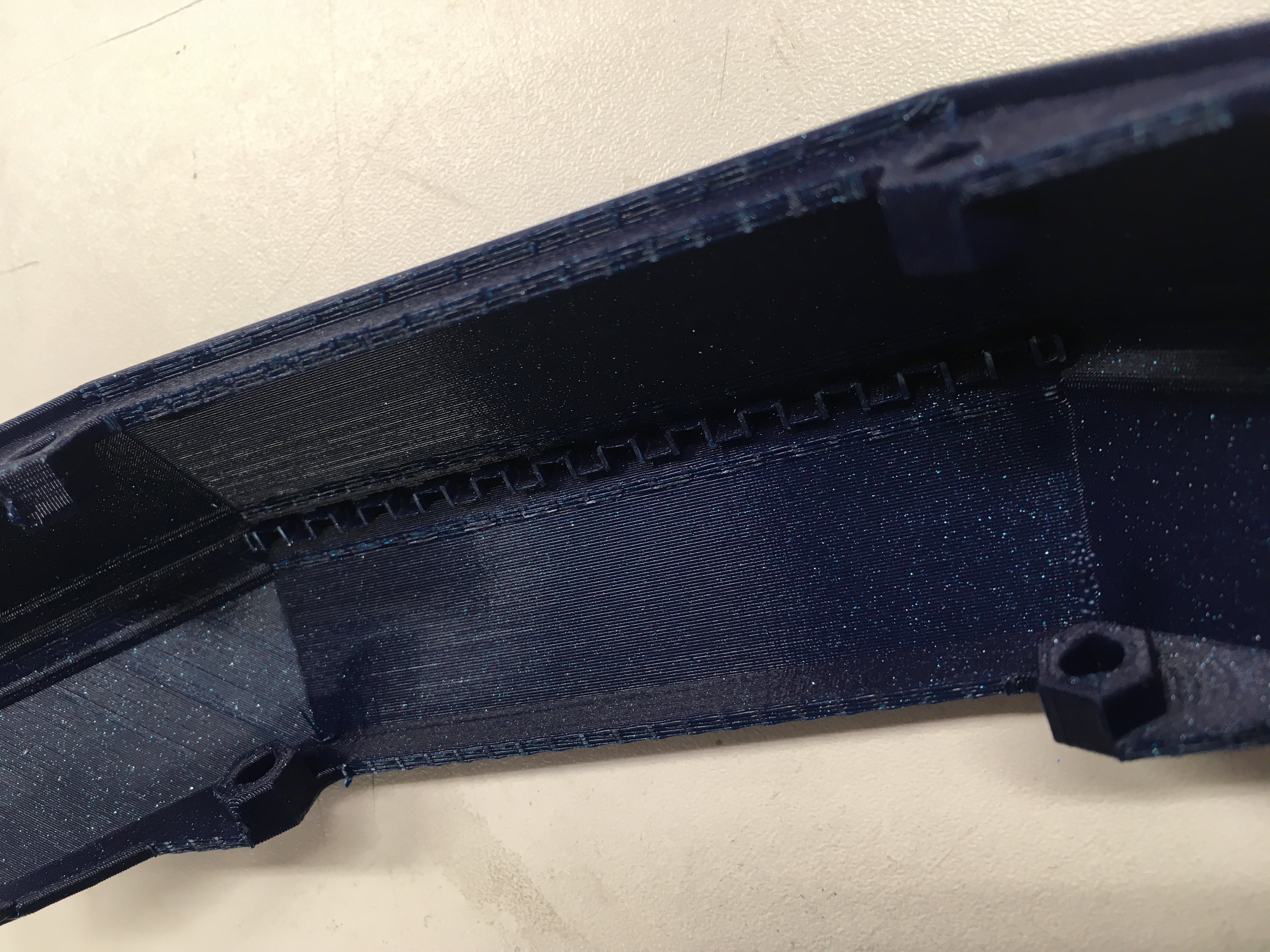
The first success of the week was when I, after a few failed attempts that were all my fault for not ensuring there was proper support, managed to dial in how to print the front cover. As you can see in the image, the only supports were along the purely flat edges. All the rest worked as simple overhangs (They are about 70 degrees). I finally had to draw a super-detailed support blocker which completely determined where there was to be support and where there was not to be support. But once I admitted that this had to be done, the results were spectacular.

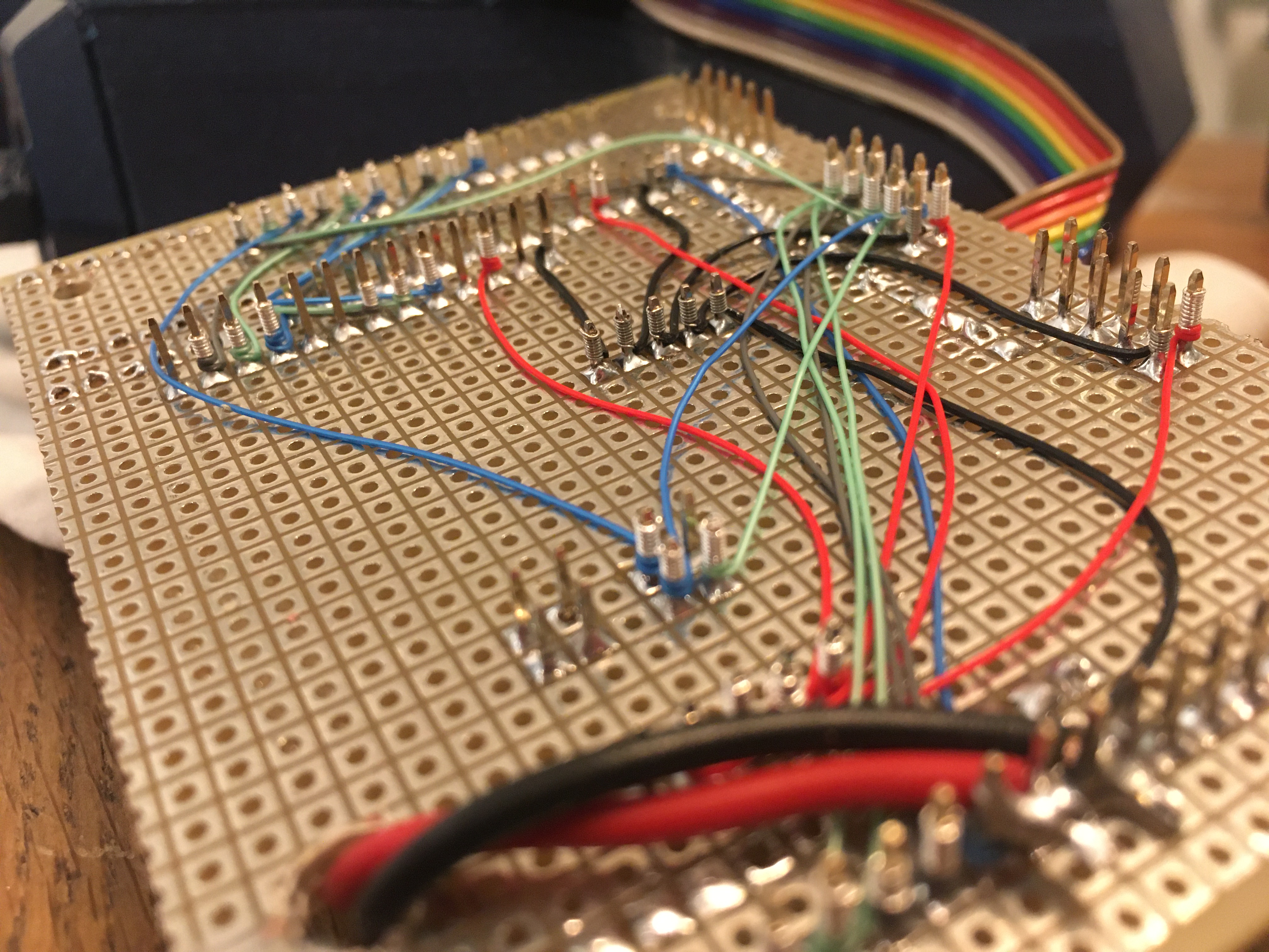
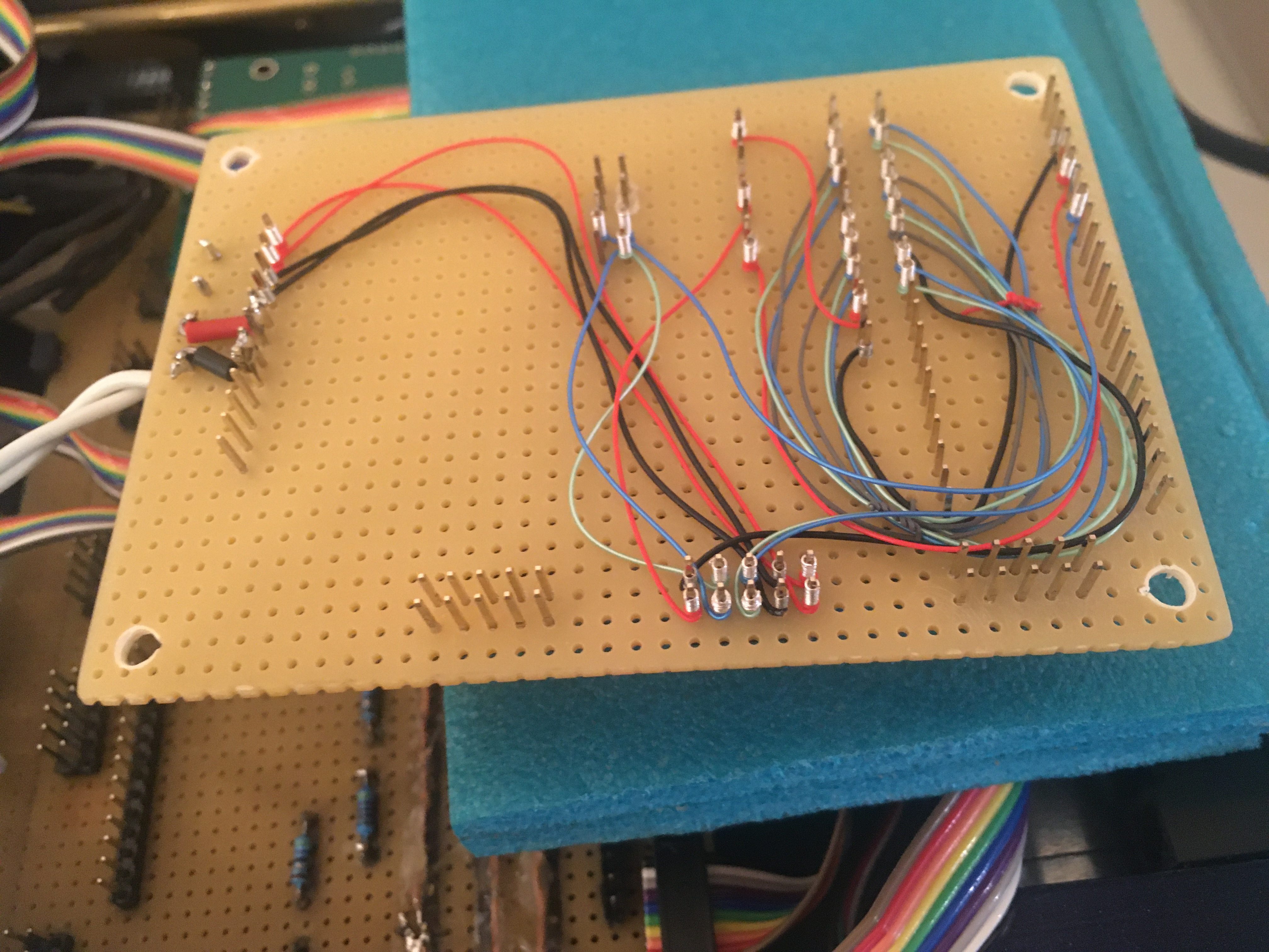
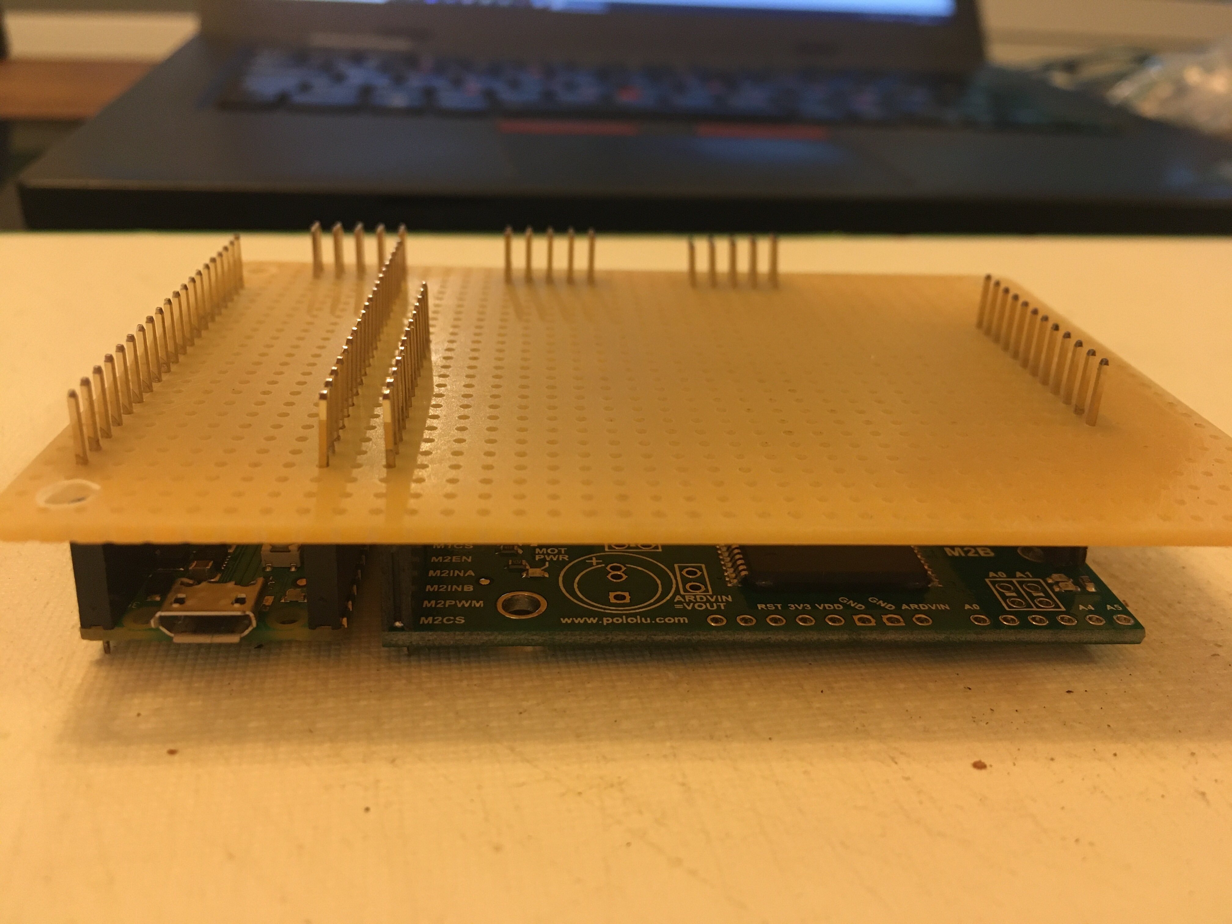
The next big thing I did was create two more driver boards. After having miscounted a pin on the first one which led to the motor not running at all, the rest went almost without issue. Here is a work-in-progress image of one of the driver boards. Can you spot the stupid error on this one?

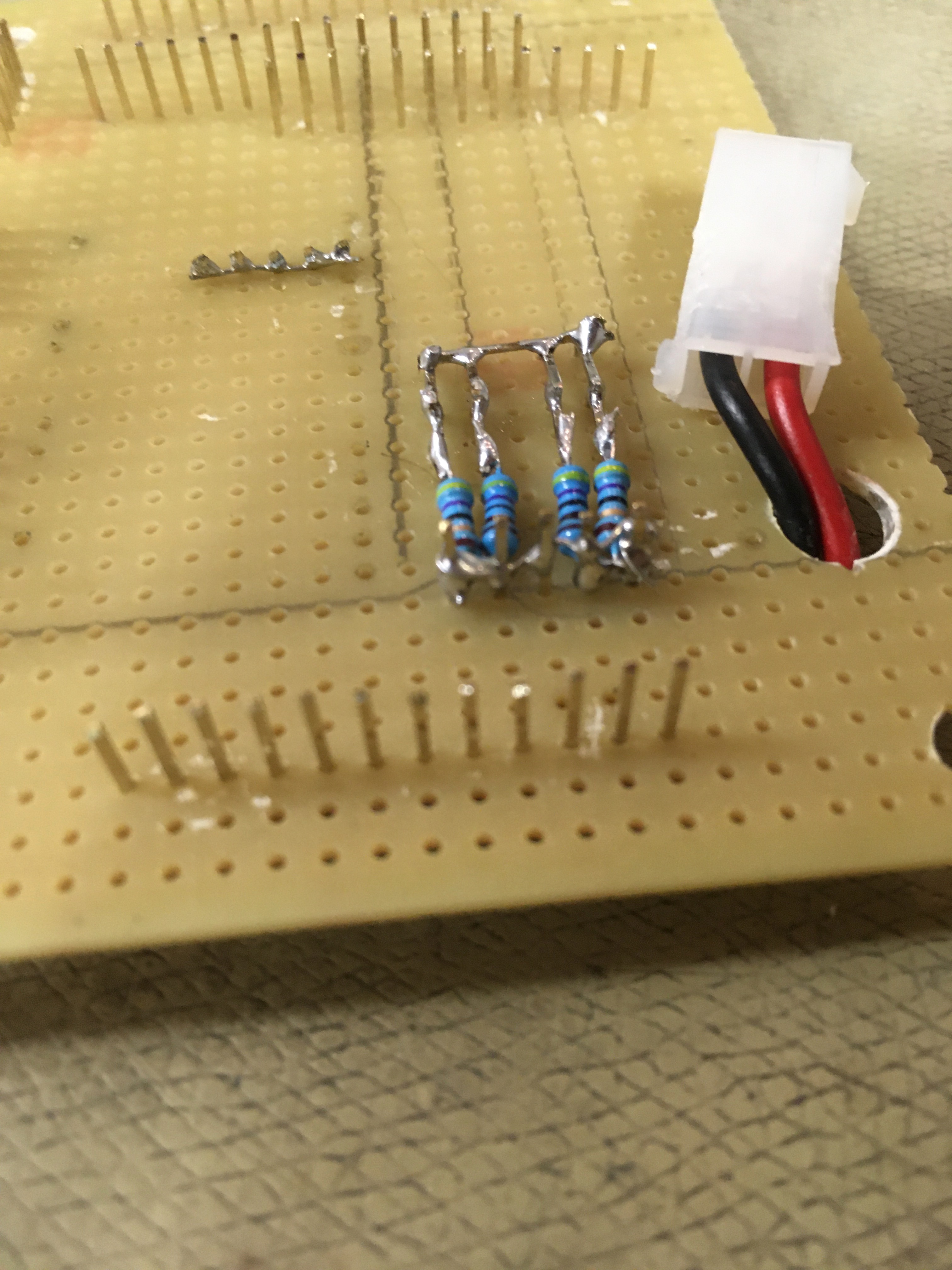
If you look closely, you can see that the small bank of 4 resistors are wired together on both ends. Yeah, sometimes you wire resistors in parallel, but this was not a case like that. That was a lesson in allways controll-measuring your connectors before running them. Fortunately, there was no damage.

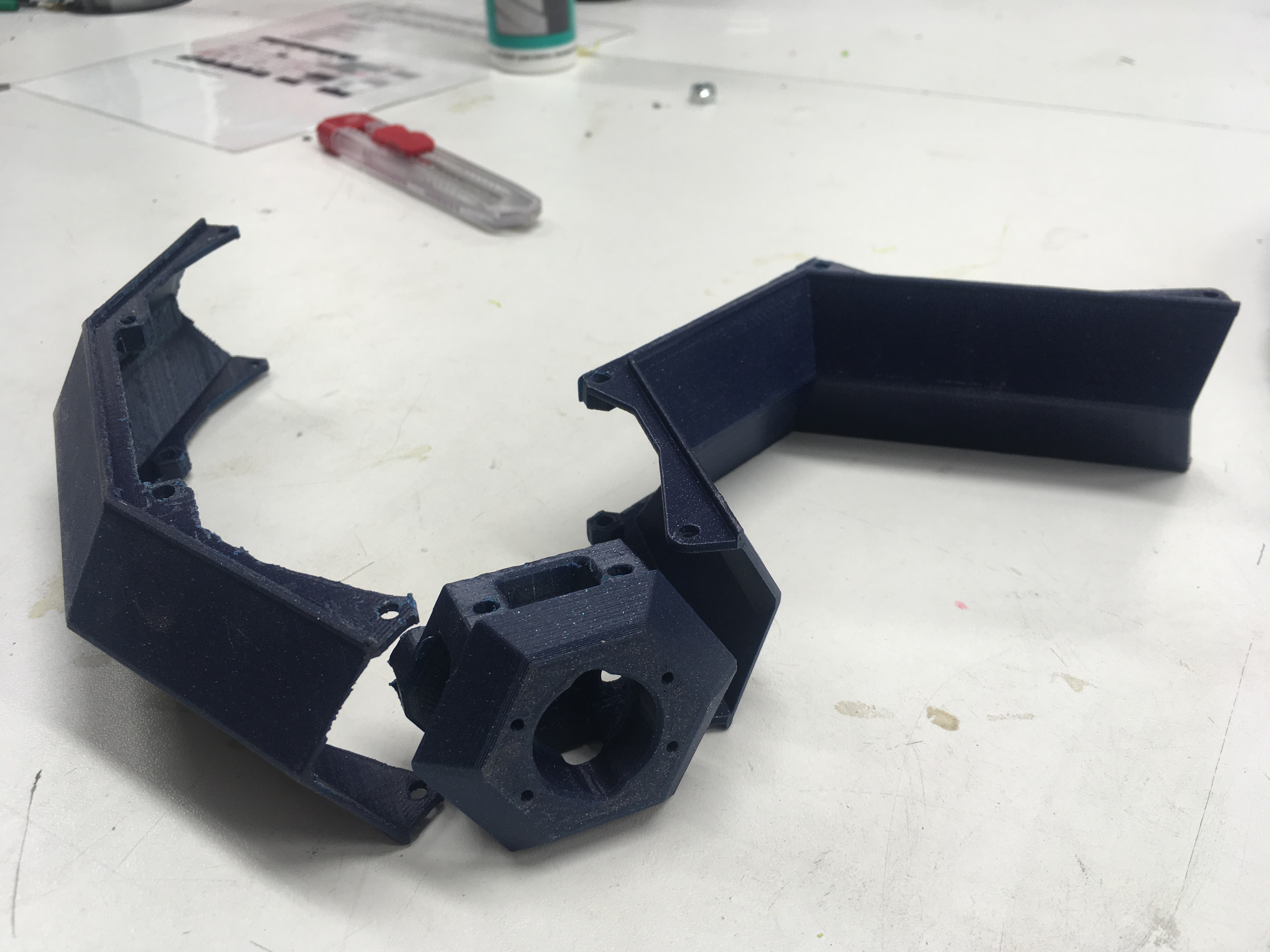
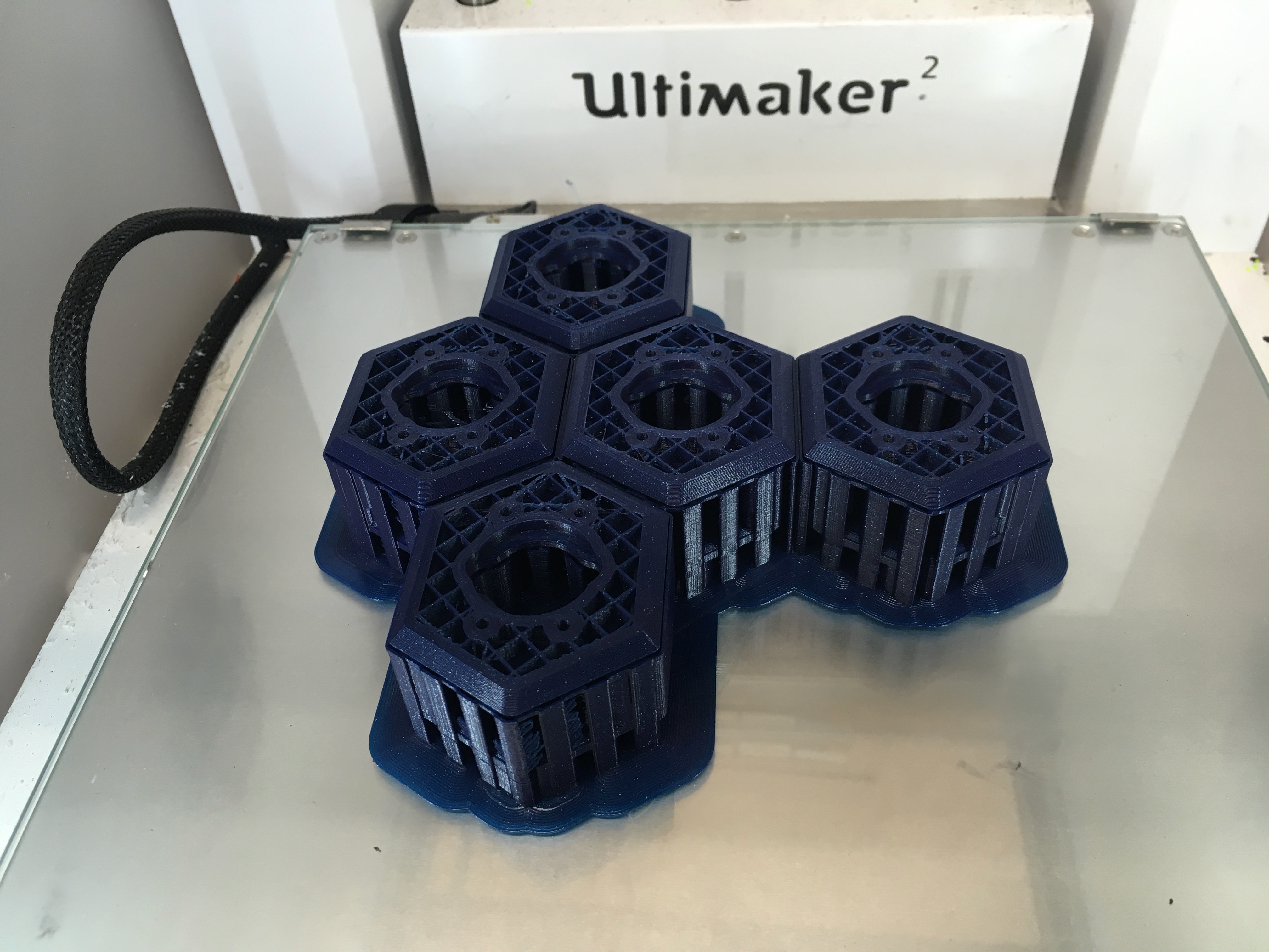
A third major component that was missing was the additional covers and leg join chassis. The covers printed perfectly the first time. The leg joints, though. There are pretty solid and rather complex, so they take forever to print. First two Bowden tubes fell out which stopped the prints. Then some really wierd issue happened, twice, where the printer simply fed back the filament and then continued printing as if all was fine. The theory is that the SD card was getting a bit old.

Here you see the last half-completed print. It is something like 90% done. Forunately, Erifor helped me out and showed me how to restart the print, and he tells me that the final pieces are now successfully printed. Will pick them up tomorrow.

Oh, and he cut out another cover with the laser for me, so I owe him twice.

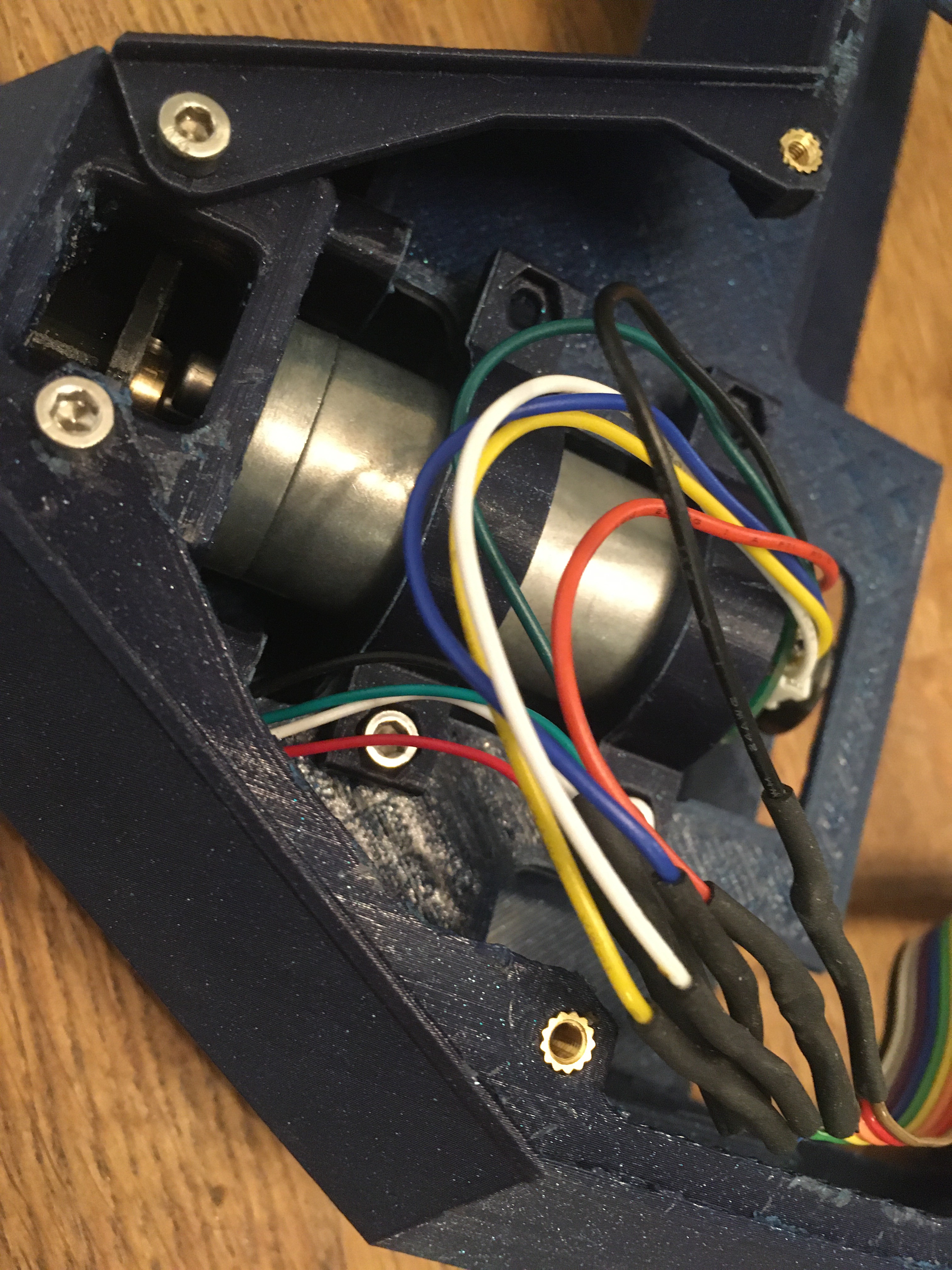
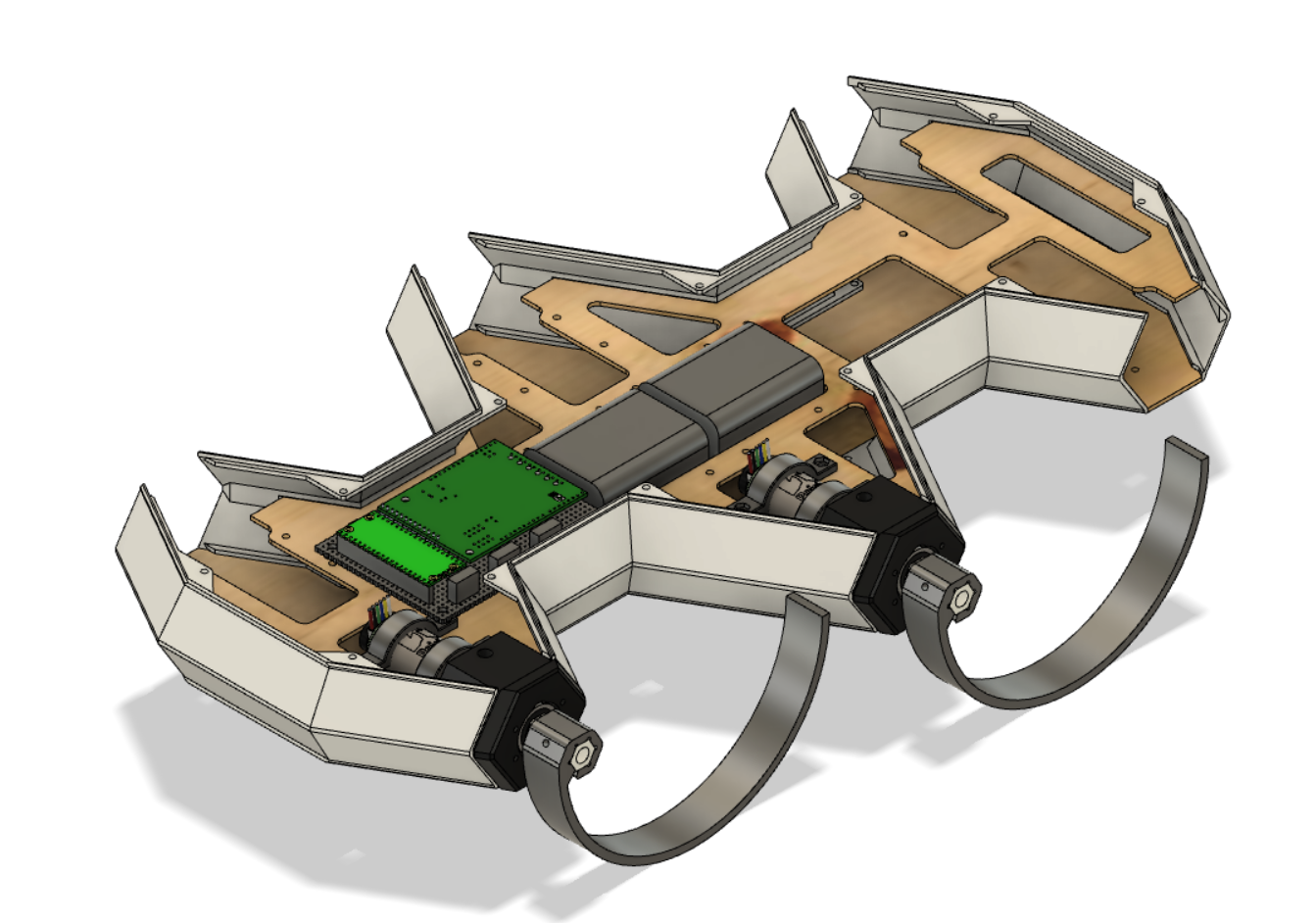
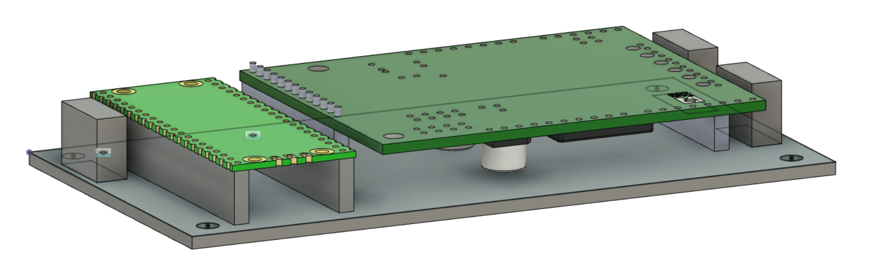
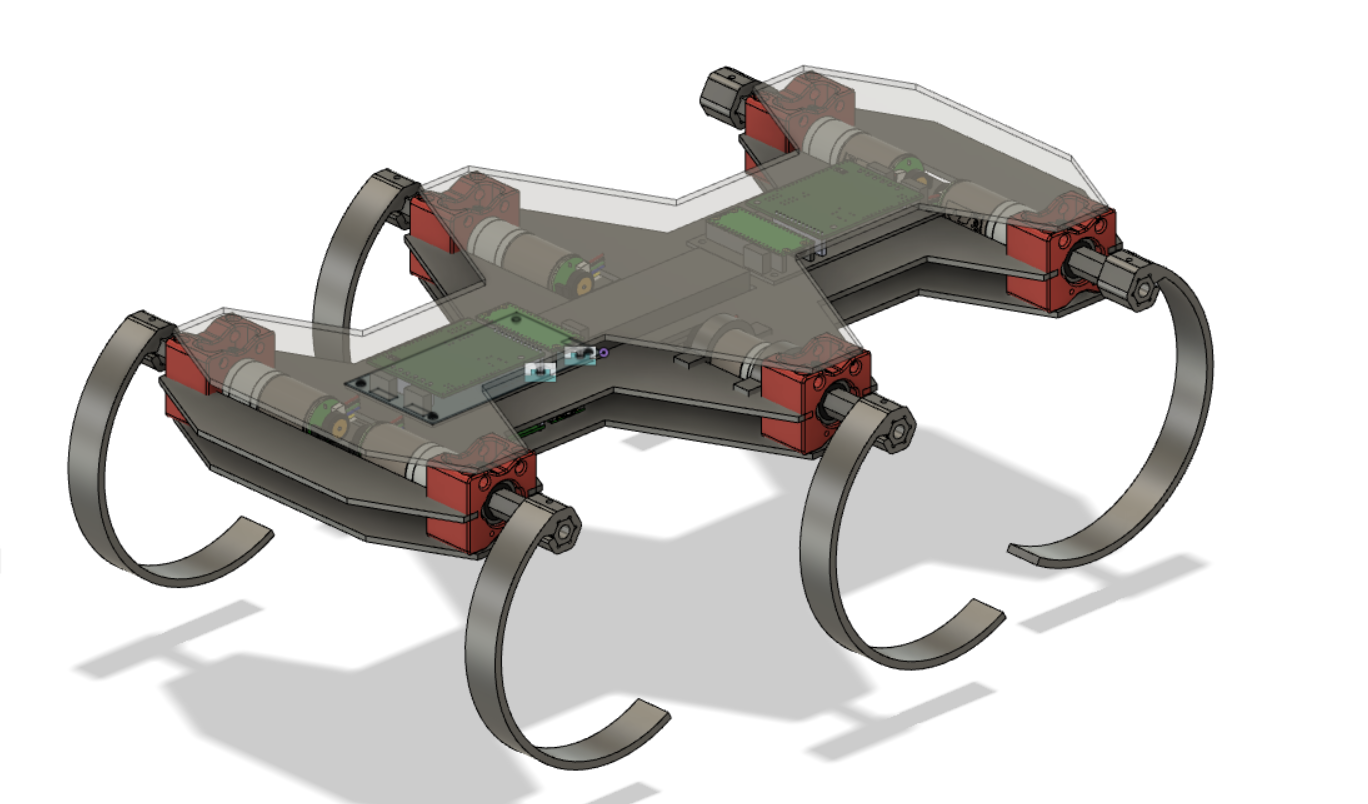
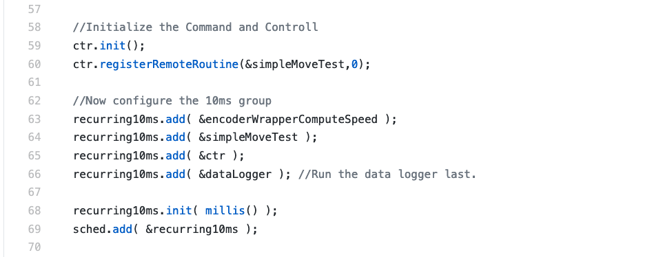
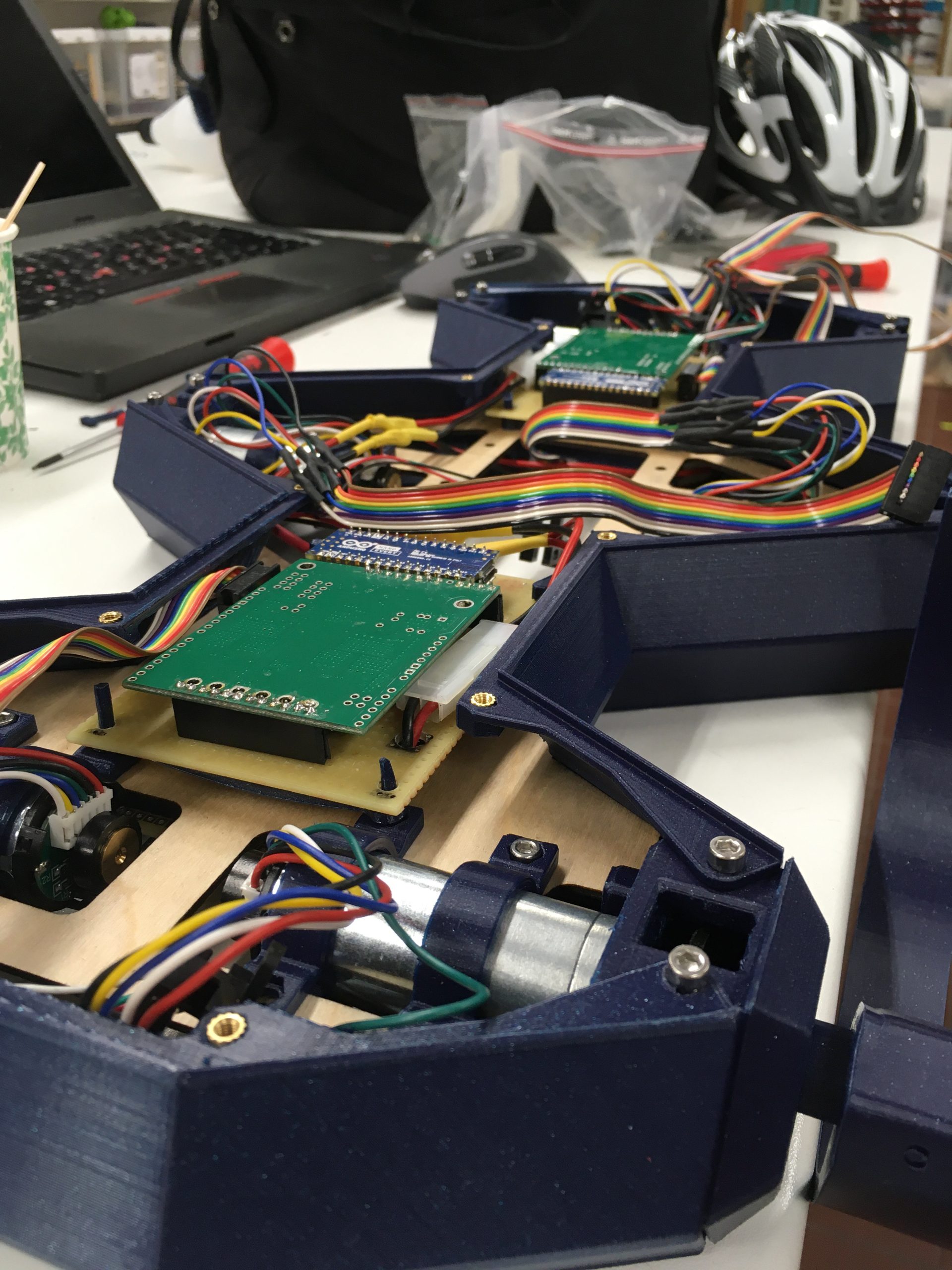
With that, I could assemble the whole thing. You can for example see the pins that I drew and printed to attach the driver cards. I will replace those with long screws, but I didn’t have any.

Also, you can see the power cabling if you look carefully. If I connect all three driver boards, then they reset right after start, so I think I will need a more powerful power adapter. I will have to measure the voltage drop as I power the machine and see if that is the real issue here. But for now I can still power up with two driver boards and that is enough.

Oh, and I also created the inlays for the case. No picture of that right now, so that will have to come next time, if I remember.

New low-profile electronics

So the Raspberry Pi Pico could not handle the flow of interrupts. So it is back to Arduino.

Also, I realized that I can make the electronics slimmer if I solder the pins and remove the plastic bar. So this is basically back to what this looked like long back.

But it is modular now and that will be such a relief. Motors work, but the encoder is misbehaving. Will have to figure that out.

Putting together the sides

So today I picked up the pieces. Lots and lots of support, yes. But after some effort, all of the support was gone.

While I cleaned up the support, I made a simple mock of the center plate, just to get a feel for it. I went with a mesh patterns to reduce the ammount of material and time. But for some reason, Cura thought it should do each square invidivually rather than do an infill-stype cross pattern. But the print still took only 50 minutes.

Finally, after adding the threaded inserts (What a joy! So easy!) I could screw the entire side together. Does this look professional or what?

Back to the space!

So back to the Makerspace for the first time in a while. The plan was to start a print of the mechanical parts and possibly experiment a bit with CNCing in plywood.

The 3D print looks like it is off to a good start. I could only find a 0.6mm nozzle that wasn’t broken but that is close enough.

As for the CNCing it seems that the router is still not done. Oh well, looks like I will have something to do this summer. 😀

Off to the races again?

So a bit of experimentation with the modular motor controller gave some very promising results. So I have now orderd all of the material and hopefully I can now rebuild the model using the new and improved designs.

And here we have the 3d-printed parts all set up in Cura

Oh, and here is the motor driver module with all the cables for one motor.Way cleaner than the old design. Also, The Raspberry Pi Pico is a joy to work with. Sure, it is cheating to have that much Power and RAM, but it really does make the programming a breeze. I mean, just the fact that you have dynamic memory….. 😀

Start from scratch

So I was doing rather well on the algorithms. But then I wanted to check that all six legs worked well. Suddenly stuff started behaving strangely with motors and encoders not working. Probably some form of short circuit or something.

I have had a hunch for a while that my design contained two many onprotected open wires that could lead to any and all forms of strange behaviour and busted components. So I decided to give up on that design and rethink things from scratch.

Step 1 was to look at the driver component. Rather than build one large one for all the drivers controlled by one massive and expensive Due, I realize that the smaller microcontrollers are a lot cheaper. The Pi Pico is extremely cheap, and runs Python. So I have decided to give those a go.

Here we see a rather compact driver unit that can power two motors. It just has power input and a single communications input. SHould be a lot more robust and easy to debug.

With this type of design, I can also make the chassis a lot simpler and strurdier with milled / laser cut flat sheets.

Here is a quick sketch. I haven’t redone the legjoints, so they are just the old ones put in as placeholders. As you can see, the whole robot gets a much more centered look. Also I can place a LiPo battery right at the center to get minimal moment of inertia, which I think is a good thing.

Unit tests FTW!

So after spending a whole lot of (Very enriching!) time building a dynamic system to be able to control the drivers and run test with configurable parameters over the serial, I realized that that was just completely hopeless on such a tiny device as the Arduino. With no dynamic memory to speak of, trying to build a flexible dynamic system is just doomed to fail.

And then it hit me. I am trying to build testable code… and in extension a testable electro.mechanical system. There is a tool build for this: Auto testing. And that is one of my favourite software development tools of all time. And given that I don’t have access to a proper debugger, basically the only tool I have access to other than trial and error.

So yeah, I chucked out all of that nice flexible code and started writing my first unit tests. But they really won’t be unit tests, but integration tests. The challenge here is not to test the code per se, but the interaction between the code and the hardware. Checking things like if all wires are properly connected and that no components have broken is even more important than testing the code itself.

So the first unit test is a simple loop that starts the motors at a given power for a given time and checks that the encoders report that the motor has moved a reasonable distance. Because without that, nothing else will work.

So this is where I will be spending a lot of time now. One step at the time building up the core features, one test at the time. But then, that is the only way to properly develop software, isn’t it?

Coding, coding, coding…

Yeah, so no visual update today. But now I am in the coding phase. So far, this is what I have gotten done:

  • Homing code that can be run in the main loop as the Uno only has 2 hardware interrupts and I need 3 for each leg.
  • A robust proportional regulator that runs the leg at a given speed. The static friction in the motors seems to be pretty high so they need a bit of a kick to get started. The P-regulator gives that initial kick and can then keep the motors moving at very low speeds.
  • A framework that accepts commands over the serial port without blocking
  • A framework to live-stream raw data from the device so I can visualize it in Matlab
  • A Matlab-script that parses the data and shows me the dynamics.

All-in-all, the motors and drivers seem to be extremely capable and go up to max speed in about 0.2s. Now I have also learned how H-bridges can break motors to a stand-still which means I can also stop the legs in a similar timeframe.

Now I just need to make sure that the P-regulator also works within the framework, and write a controller that takes the motor to a given position with a given speed.

By then, hopefully my new Due arrives and I can wire up all 6 legs. Then it is off to the races!