Vad är nästa steg?

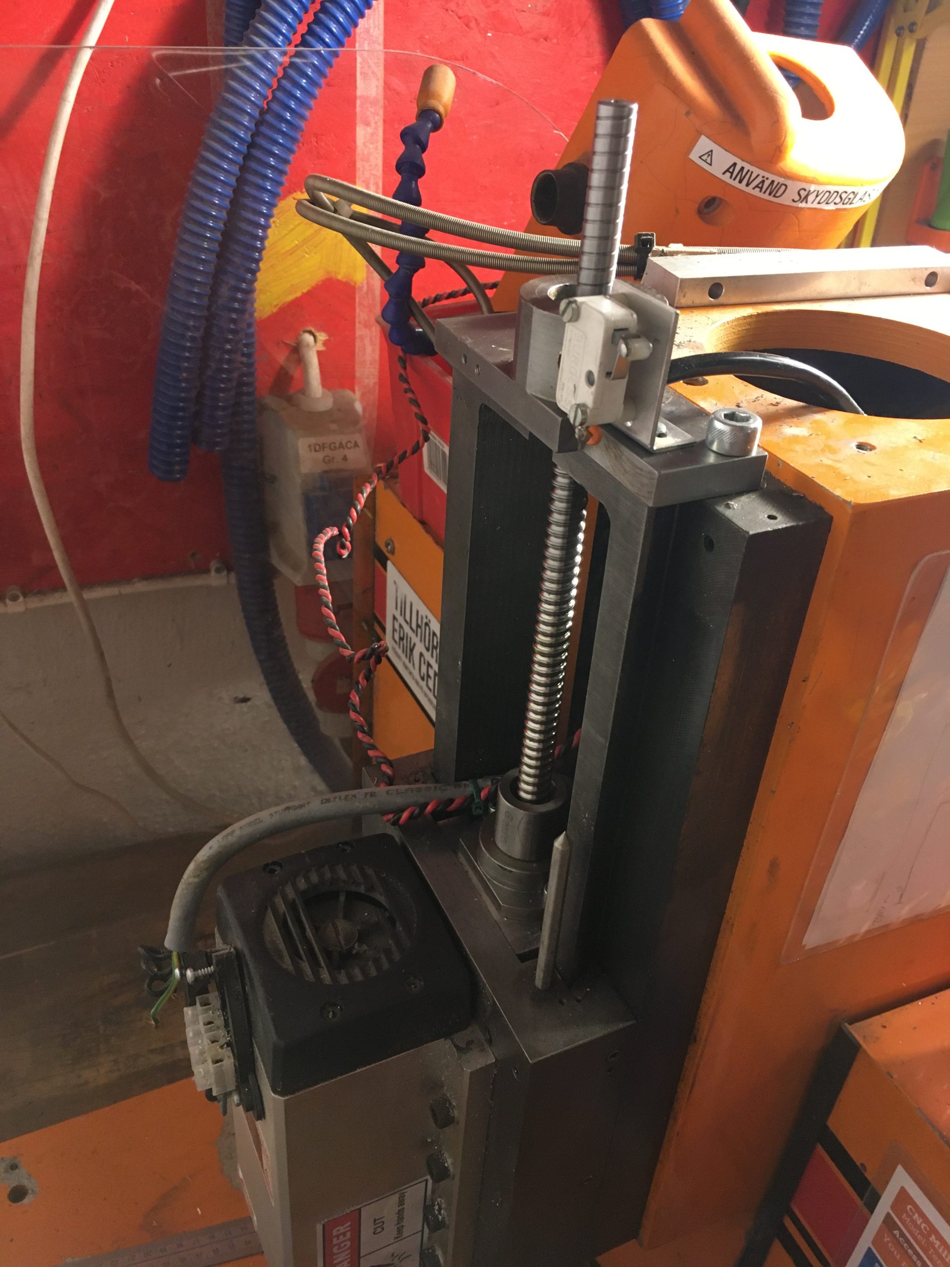
Z-axelns homing switch

Det ser ut som att det är så här den skall sitta, men då når inte pinnen till den innan kulleden går i taket.
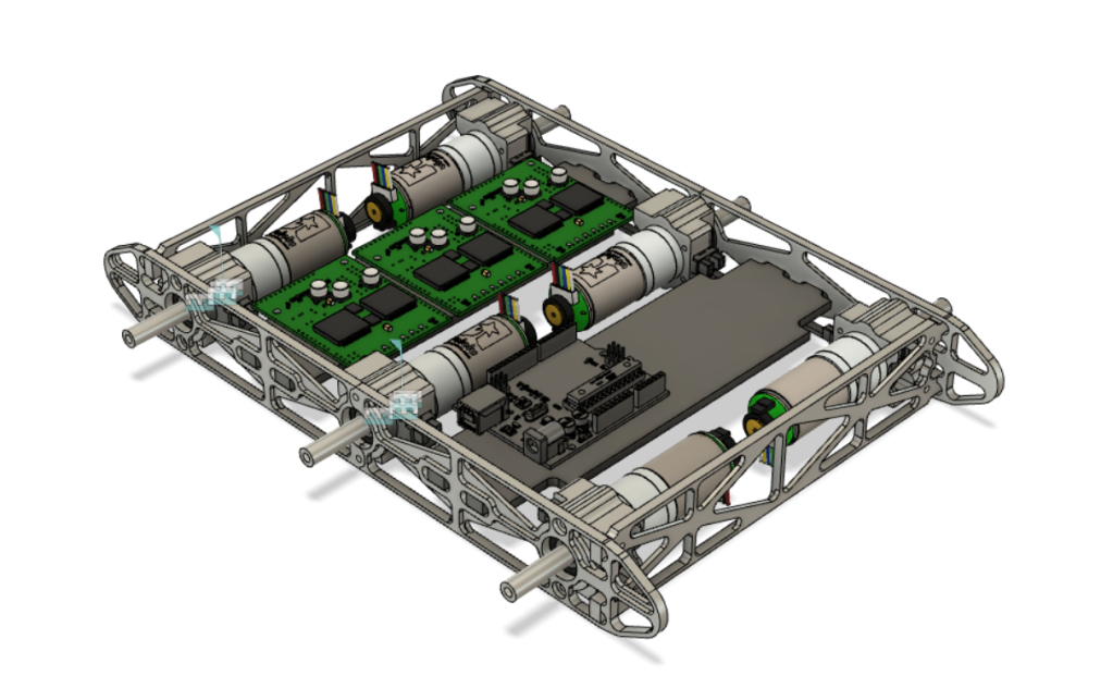
Z-motorns hål

Vad är bästa sättat att göra hålet i aluminiumchassit stort nog för motorn att gå ner? Helst skulle jag använda en liten handhållen sticksåg med metallblad. Finns det en bättre metod?

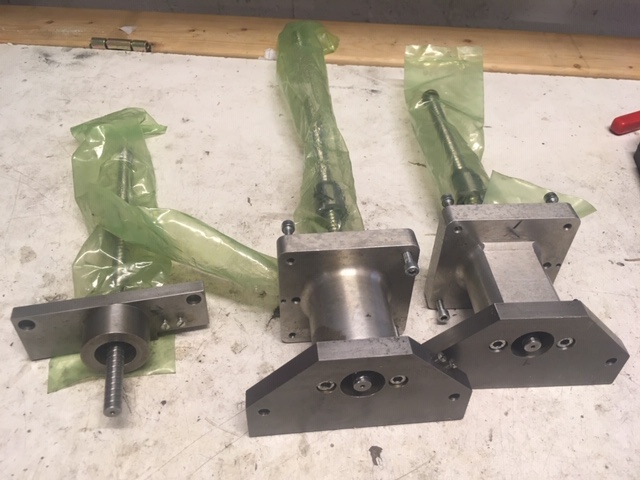
Y-axelns montering i chassit?

Jag kommer behöva montera isär och ihop både X och Y-axlarnas lagerhus för axlarna pekar ut ur fel ända inser jag nu. För åt minstonne Y-axeln så behöver jag dessutom montera isär den helt och hållet en gång till för att alls kunna gå in den.

För jag antar att det är helt orimligt att skruva av skruven på kulaxeln? Då lär alla små kulor rulla ut och vara helt omöjliga att sätta in igen?

Jag är lite orolig att axeln kommer vara svår att trä genom alla hål frå utsidan även om jag tar bort alla lager, men vi får hoppas på det bästa där.

Inga kullager för X/Y-axlarna?

Är det så att det inte är några kullager mellan de tunga metalblocken som utgör själva X/Y-axlarna? Man bara smörjer och spänner åt med skruvarna så att det blir lagom lite glapp?

Completing the driveshafts

Todays task was to complete the driveshafts, ensuring they are completely stiff as well as adapt the axeljoints to fit on the motors. This turned out to be more interesting than planned.

The first step was to test the bearings I made last time and ensure the were properly shimmed and were completely gap free. One of the shafts needed one additional 0.1mm shim. Now they are all three rock solid. The flex in the construction is smaller than the flex in the 10mm thick steel plate that they are attached to.

The second step was to open up the holes in the axel joints to fit on the motor axels. With a bit of careful mounting, that was a piece of cake.

But these motors need to have keyed holes. So I saw this video a while back about the “broach” technique for making non-round holes. Skip to 9:56.

So suddenly I am doing a whole handful of firsts:

  • Grinding a piece of HSS metal into my very first custom tool.
  • Mounting said square tool in a chuck.
  • Actually successfully broaching a key slot in each of the three axel joints.

The result wasn’t particularly pretty because I didn’t grind as much on the tool as I chould have, but for a first ever I am really pleased. I feel that once you have broached a hole with a custome tool, then noone can even call you a newbie again.

Finally all the pieces for a complete driveshaft for an axel. And below we have the Z-axel completely mounted. 😀

The Terco side-project

Seems to be my new main project for the forseeable future. Building a CNC machine is not done in a day, even if all of the parts mostly exist… Also, I have done my first 3d-print but I will need to colect it tomorrow as it did not quite complete before I had to go home.

So today I started with the rebuild proper. A run-though by Eric Cederberg about which parts belonged where, and I got working.

Cutting down the fastening collars to the right width.

Above you see the fastening collars that will attach the ball screws to the bearings. These carry all of the force of the movements, so getting them to exactly the right size for a snug fit in the bearing houses is critical.

To make sure the collars do not start slipping after a few years, we decided the drill through the collar and ball screw and fixate them with a spring steel pin. This was really scary as the ball screws are custom made in Asia meaning they are expensive and delivery times are long. Obviously, we had no spares.

Drilling through expensive ball screw rods…..

Either way, the goal was to get the entire assembly to be about 27mm wide, and I find that the tolerance achieved is perfectly OK. 😀

Allways nice to achieve 0 tolerance

So below we see the status right now. Three ball screws securely fastened in their bearing houses and the most critical part of the build is completed. Note that the Z-axis bearing house is not actually assembled as the other part of the bearing house is stillf astened to the machine.

Final results for today

So that was a good first day. Next steps are:

  1. Drill out the motor holes from the axel joints so they fit our motor axels.
  2. Fasten the axel joints onto the ball screws. This requires disassembling the bearing houses above. When doing that, the shims should be rechecked. I believe that one of the bearing houses perhaps should have 0.1mm less shims and the other 0.1mm more shims to be perfect.
  3. Open up the gap in the Z-axis mount plate on the Terco a bit more as these ball screws seem to be a bit wider than the originals so the Z-axis cannot actually be mounted as it is today.
  4. Start assembly of the Terco.

Cleaning up the Terco

So the Terco was not going to do any more work until it got some love and some spare parts. The spare parts are still on their way, but the love was availible here and now.

The insides of the Terco are jam packed with cables and electronics. Three power converters, a complete computer, three drivers, and an inverter to drive the spindle. Not every single cable connecting all these parts together had been done in cleanest of ways. I even found one original cable from the 70s. The rubber was fascinatingly different from what we use today, and was cracking completely.

Red original 1970s cable cracking simply from old age.

For one, the power converter for the display was stored inside the case, with its power cable sticking out through a gap in the case. Not particularly elegant. So I decided to cut that cord and connect it to the 240V power we allready had inside the case. And there I was reminded why you should never have multiple power sources connected to the same machine. Cutting off a live 240V cable doesn’t only blow a main fuse. It also converts your side-clipper into a wirepeeling clipper in a puff of smoke. But now the screen gets power from the main power cable that drives the entire machine.

So today, I opened it up completely and resoldered, shrinkwrapped, trimmed and gathered the worst of the cables. Now all cables have the proper length and there are no unnecessary sugar cubes or temporary extensions. Also, the motor driver fan only turns when the drivers are actually powerd, unlike before when it started as soon as the main power switch was turned on.

Looking at the image below, you may wonder if this is what “tidy” looks like, and all I can say is that this is very much better than it was before.

Finally, the Terco got a proper vaccum cleaning and a proper alcohol wiping of all internal compartments. Now it is ready to get brand new motors and hopefully become aven better than before. 😀

Or not….

So today, the plan was to start mass-producing frame parts. I need a total of 4 side frames and two front/back frames. The plan was to make half of these just to see that it all fits together.

Unfortunately, this is what the CNC machine looks like now. One of the motors has given up and needs to be replaced. New motors are ordered and the machine will be rebuilt, but it will be about 2 weeks.

So I spent a few minutes in the wood-shop and made a frame to mount the motor testbed in and went to work on the regulator. So this is what that looks like now:

This may really be happening!

So today I knew that I needed to finish one of the motor mounts, complete with bearings and opto-switch and make sure that the entire electro-mechanical setup actually works. And yes, it really does!

[vimeo 374277351 w=640 h=564]

So yeah, the video just looks like a motor starting and stopping, and admittedly, that is what it is. But the rotary encoder on the motor is actually used to rotate the motor exactly 0.8 revolutions via a P-regulator. And now, the opto-switch is also conected so the arduino is detecting every time a full revolution is completed.

So next time I sit down and write serious code, I will have to write an init routine to make sure the motor knows its absolute position as well. But that is just a question of lots of lines of code, so that can wait.

Another thing I realized today is that when you try to miniaturize your design, it actually becomes very small. When most of your dimensions are counted in single digit millimeters, things get delicate. I was really worried that the lathe would not be able to actually produce the rotary disk for the opto-switch. But after a few incidents of the part jumping out of the lathe, I finally managed to be careful enough to get a piece of the right size.

So I will end with a close-up of the motor mounting block. Everything snuggly in place with no wasted space. The rotary disk isn’t fastened in a good way which I need to figure out how to do, but the rest feels solid.

Starting a blog

So all of the previous posts were written in one go. So why did I decide to document my process just now?

Well, because I just saw this clip by Bernadett Banner, a costume historian whose video blog I found recently and which very much suits my personality. Yes, historical dressmaking and programming machines to cut metal into pieces that will become a semi-autonomous robot. This is 2019, and I don’t need to limit myself.

Anyways, back to the video I saw. Here it is:

https://www.youtube.com/watch?v=jMGyfkvY06g

I mean, just listen to Cathy Hay’s voice. Did you ever hear a voice so steeped in passion? And it ends with the wonderful quote “Oh, and go do something impossible today”. Yes Bernadette. I will.

Or rather, even if I now realize that this robot project of mine is way harder than I had planned and is going to take a year or two (Or more if I decide to add cameras and teach it to hunt in the night), it is nothing compared to that dress. But impossible was never more than a shade of gray.

A close shave

So armed with a new design, It was back to the makerspace. Results were mixed to say the least.

In order to not once more find that I had designed something that could actually not be built, I decided to mill a prototype out of plywood. I had a hunch that is might not work, and boy was I right!

Promising start…

Everything worked out really well until the final finishing passes when then forces from the milling simply lifted the pieces out from their frames and shredded them to splinters.

But no joy….

In the mean time, I tried to mill one of the motor fastening pieces in aluminium. The mister was broken so I used som manual compressed air and alcohol from a squirt bottle. It turns out that that is not nearly as good as having a fine mist of alcohol and air continuously flowing. Twice I had to pause and remove gummy aluminium from the flutes of my mill, but nothing broke at the piece came out as perfectly beautiful as I had hoped. 😀

In order to handle the tolerances, I actually told Fusion that my end mill was 0.1mm smaller than it really was. That worked well as a hack.

I made one mistake, though, and that was forgetting that my ball bearings are 7mm wide and not 8. But fortunately I can fix that by simply removing 1mm off the top of the piece next time.

A fresh start!

So my original design has some serious flaws. Going back to the drawing board, I decided to start completely from scratch.

I had two problems. The first was that all of the screws were not as accessible as I needed them to be. The second was that the fram required me to drill holes into the short ends of the front and back walls. This would have required a manual step and I could never get good enough tolerances on that.

Besides, anyone can design a machine that is hard to build. Making a machine that can be manufactured using a minimum of steps and realignments is the challenge. So what I wanted was a design where the motor mountings were the only pieces that required milling from more than 2 sides.

So here is where the magic happens. By using the motor mounts for corner support I think that the design will be completely solid. By adding a few extra interlocking edges as well the screws will not be the only thing keeping the pieces together meaning absolutely nothing should move.

Speaking of movement the side walls should be able to take a load of 25kg without buckling. Aluminium really is a fantastically strong and light material. I see why they build aeroplanes from it. We are after all talking about a structure mostly made from bars that are at most 4mm thick in either direction, most are 2mm thick in at least one direction.

To top it off, here is a rendering of the entire design.

Just because you can CAD it….

Does not mean that it will work in real life. So I had made sure to leave enough room for the screw-heads needed to assemble the piece. I also had a plan how to be able to reach with tools to be able to actually fasten the screws. All except two…

So it is back to the drawing board……