Superglue!

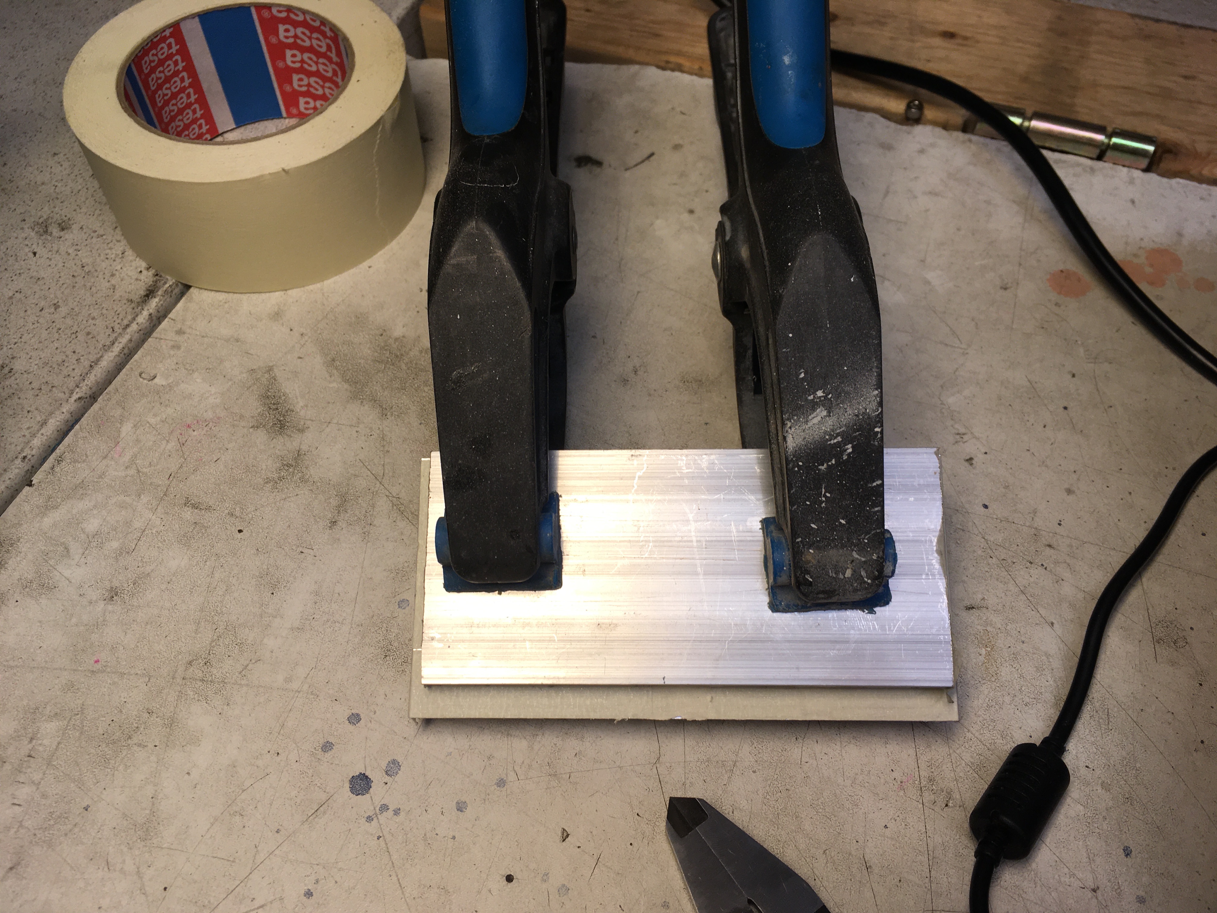
So first attempt att making a real part today, and on top of that I wanted to try the new superglue+masking tape method. Many have spread the word about this method, but NYC CNC do it best, as usual:

The problem is that none of the products they mention can be bought in Sweden, and even their links to Amazon are getting stale. So I tried TESA Premium Classic masking tape and Loctite Power Flex Gel. I gave the glue a few minutes to harden properly below.

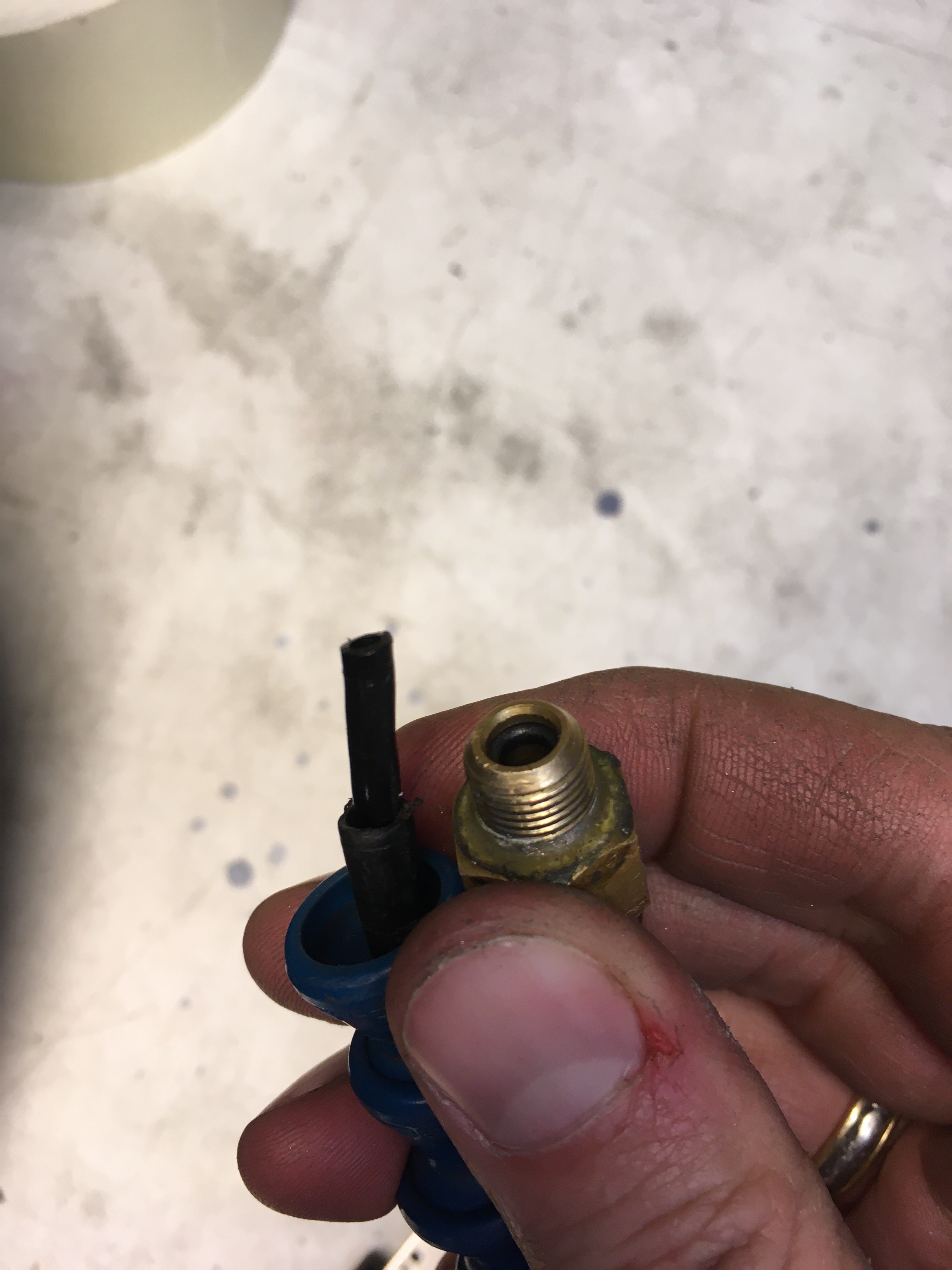
Then I noticed that the mister wasn’t working. So I had to take it apart. It seems that the O-ring does not grip the inner tube properly, meaning pressure air leaks into the space where the alcohol should run. Forcing the tube to become a little wider by forcing a 2.5mm drill bit into it seemed to do the trick. Now it sprays a fine and stable mist.

So mister was fixed. Time to see if the glue method really worked…..

Worked like a charm! Part came out just the way I was hoping for.

Lessons learned:

  • CNC-ing is an expensive hobby. Jogged a 4mm end-mill straight off while touching off. Great start…… fortunately, I had a spare.
  • Assuming that the top of the spoil-piece will be perfectly square with the machine once you mount it is a bit naive, give the types of equipment I am working with here. Next time I will place the spoilpiece in the machine, polish off the top to ensure it is flat and square, then glue the stock while the spoil piece is in place in the machine.
  • Using tabs was a great idea. With the super-glue method, surface area is everything. By using a contour with tabs to finish off any pockets that go all the way through, any pocket large enough will get a piece in the middle that helps keep the part down.
  • Getting tape-glue into the end-mill is probably a really bad thing, so next time, I will add a second layer of masking tape to n open space on the spoil-piece and touch off my z against that. This should mean that the end-mill will not mill into any of the actual tape. Worst-case scenario, the end-mitt doesn’t go all the way down through the metal, but the remaining piece will be so thin it does not matter. I can cut it with a knife, even. I will still have to file down the tabs anyways.

Open heart surgery

So it was quite clear last time that something had gone wrong with the Y-axis. It really was moving back and forth a full 0.1mm with a distinct click to it. So I opened up the machine again and pulled out the Y axis ball screw (Getting rather good at that by now :P).

The nice thing is that I realized I could do this without affecting any of the calibration of the machine. Just slide the X-axis over a bit to expose the Y-axis ball screw fastener bolts. Once done, reattach the Y-axis, slide back the X-axis and atach the X-motor to the bed. And done!

The issue causing the backlash seems to be that the spring steel pin wasn’t being springy enough and the screw bolt was not attached to the bearing fastener. What to do?

Fortunately, I found some solid metal pins of the right dimensions. With 8 layers of aluminium foil forming a shim, and some bearing glue, and the beasing fastener was rock solid again. Reshim the bearing house with an equal 8 layers of foil and put all of the pieces back together again.

Now the Terco has a backlash of 0.01 in Y and 0.02 in X. Unfortunately, the entire chassis is a bit springy, so the total flex adds up to something like 0.05mm. But at least we can now confidently say that the Terco performs at less than 0.1mm error in all scenarios.

Finally, the inaugeration of milling with the 4th axis. It worked like a charm! At least until I ran the end mill right into the chuck and ruined the mill and made a big mark in the chuck. Lesson learned: When doing 4-axis milling, model your chunk into your CAD model so you can verify that you are not cutting into it.

Also, Delrin is not as solid as I had assumed (Obvious in retrospect) so the vibrations were completely unreasonable if this had been anything but a test cut part.

Squared and inaugerated

First up, I felt that the acceleration I set before was probably not the maximum possible. So now we have 6000mm/min and a full 1000mm/s2 in acceleration. That is pretty stiff.

About an hour of work later, and both the vice and the fourth axis are mounted and squared.

One thing is not great, though. It seems the the Y axis bearing has somehow set and now has a full 0.1mm backlash. I guess that I will have to take it apart and fix that. Fortunately I realize I can do that without affecting the rest of the machine. But I still need to remove and reattach the ball screw. So not very happy about that.

So for now it has an official tolerance of about 0.1mm all included. So I felt I neede to actually do something with it.

So if you can see it, the Delrin piece has a big hole in it. It seems Fusion starts each program with a g53 move to z0. Now I had configured 0 to be at the bottom of the range. BAD IDEA. Had this been anything other than plastic, I would have been one endmill poorer right now.

But I did manage to fix one more thing as well. Now the Linux CNC accepts a tool in the G-code. So no more custom processors.

Et voilΓ !

So done I am and the Terco is ready for work. Kudos to Scott who helped me on the home stretch with the X motor box and the Z bellows.

Here it is. πŸ˜€

To make sure we get the most out of the new motors, I trimmed them as well. Six times higher max speed and significantly higher acceleration will really cut down on the milling times.

But then, who does 3 axis CNC these days? When we have an A axis just lying around. Some alignment later and we have that squared up as well. πŸ˜€

Not only did I get the machine up and running including the A axis. I also machined the firs part on it.

This is a small collet to fasten the leg joints I will be making as I will need to mill right up to the joint fastener and I need some space so I don’t cut into the jaws.

Almost there….

I have to say that few tools are as satisfying as the angle grinder. Yeah, you know what I mean. πŸ˜€

So today the plan was to complete everything except the cover box for the X axis motor. And that is almost what happened. I give you the Terco with only the Z bellows and the x motor cover missing.

I had planned to use the Portal CNC to make fasteners for the bellows, but then I found an original piece in metal at the same time as the Portal CNC refused to start. So I made the pieces using sheet metal and the angle grinder. Quick, elegant and satisfying.

Next time, I will just continue and do the Z bellows using the same technique.

Also the X motor cover unless someone else does it.

And shorten the M6 screws they hold the inner Y bellows because they were too long.

Then the last configurations are just needed and then the machine is done.

Smooth as butter, hard as rock

So the bearings were clearly too tight before and that was just not right. So today I pulled the entire machine apart and made sure to shim everything properly with aluminum foil to get those last 1/100s.

I also realized that my cheating with the bearing fasteners for the Y axis had come back to haunt me as the Y axis was both too tightly shimmed and still wiggled at the same time. not sure you can see it in the image below, but the pin does not go all the way through meaning the axel is not fastened symmetrically in the bearing holder.

So nothing else to do but pull these pieces apart and refasten everything correctly.

Now this is how a bearing should behave. πŸ˜€

Finally all pieces are back together and the wiggle is now down to a consistent 5/100. Given that many of the solid parts have a flex of about 1/100, I think this is as good as it gets.

All basic parts in their places!

So now all of the parts needed for actual operation came into place. Happy days!

First up was the X axis.

And a fee limit switches and some cable reattachment with Alvar and we have what could be a working (But ugly and fragile) CNC.

To quote an old colleague “stepper motors waking up are so cute”!

[wpvideo jc7KQ5Go ]

The next step was to check the rigidity of the entire construction….

Yeah, no breaks for me. I was hoping for about 0.02mm flex in the entire thing. Nut it was far above 0.05. That is probably worse than it was before the rebuild…. πŸ™

Y axis complete

So today was rather uneventful. Y axis got completed as planned and x axis is almost done too.

First step was to cut out a hole for the now a bit longer motor assembly. Normally, the angle grinder is the tool you go to when all else fails. Not today!

The angle grinder started on a good note but ground (No pun intended) to a halt a few millimeters in. This chassis is not made of regular aluminum I tell you. It has to be some sort of hardened version.

The manual drill saved me and about 20 holes and a crowbar later, voila!

Y axis had to be rebuilt as well with all pieces in the right location. So here it is, a complete Y axis motor assembly.

A few bolts and some nervous seconds when reattaching the ball screw later and the Y axis was done.

And here is the X axis just waiting to be attached as well.

Z-axis done and Y axis parts all done

So I really love manual machining! If the mill and lathe had only had digital readouts I would probably have used those instead.

Either way. Today the Z-axis was completed. The drive belt is tight and the cables are all nice and tidy thanks to Magnus.

Next step is the Y axis. Since the new motors have longer axels, a 25mm thick spacer was needed.

Since the motor and bearing house both have circular centering edges, I decided to add matching edges to my spacer. Putting round concentric holes I a square piece turns out to be really easy if you start with a center hole big enough for the lathe chuck to grip it from the inside.

So first make a hole.

Then make a bigger hole.

Finally, after learning even more about how to not shape turning bits, here are all of the pieces.

Final step was to drill and tap the bearing house holes to make them M6 threads. Turns out that when you are tired, you may forget that an M6 thread cannot be made in a 6mm hole….

Either way, my bolts are unreasonably long so I can use nuts instead. No harm no foul.

Here are all the pieces. Now just need to cut a hole in the chassis to fit the longer assembly and then mount all pieces together.

Z-axis completion (Almost)

So the goal for today was to finish the Z-axis. I almost succeeded.

The first step was to turn a hollow axel that I could use to change direction of the Z-axis ball screw nut. These nuts contain a large number of tiny metal balls that are tightly fit between the ball screw nut and the ball screw itself. If you unscrew the nut, all of the balls fall out, and I doubt putting them back is is even doable without proper tools or whatever they use to assemble these in the factory.

So about an hour later, after having learned a lot about tolerances and surface finish when turning Delrin, I finally had my little tool and could unscrew the nut onto it. This was the easy part….. The tape is there to stop the nut from slipping off.

A deep breath later, I put tape on the other end and removed the original tape to be able to roll the nut back onto the screw. I didn’t even have to fiddle. The tolerances on these things are amazing!

So here it is, the Z-axis ball screw with all parts in the right order and direction.

The next thing to fix for the Z-axis was opening up the hole in the chassis for the new larger motor to fit. The chassis is something like 10mm thing aluminium. Aluminium is a soft metal. How hard can it be?

Two hours later, I can say that cutting though aluminium is horrible. Everything we learn about aliminium when milling it is also true for cutting it. And none of the tools in the makerspace were really doing the job. Finally, I realized I could drill holes and cut between them. Finishng the first corner was a true victory and worthy of a photo:

And just towards the end, I saw that we had a battery drivern electric angle-grinder with a proper cutting disk. Has I used it, the entire cutting would probably have taken 15 minutes instead. Either way, now there is a large ugly square hole in the top of the chassis and the motor and all pieces fit πŸ˜€

So in summary, Z-axis is amost complete. The belt you see above is a bit loose, so I need to make the motor mount adjustable. Also, I noticed that the new motors have 6mm mounting holes while the old mechanics have what look like m5 screw holes, so I will probably drill those holes out as well and rethread them to M6 holes while I am at it.