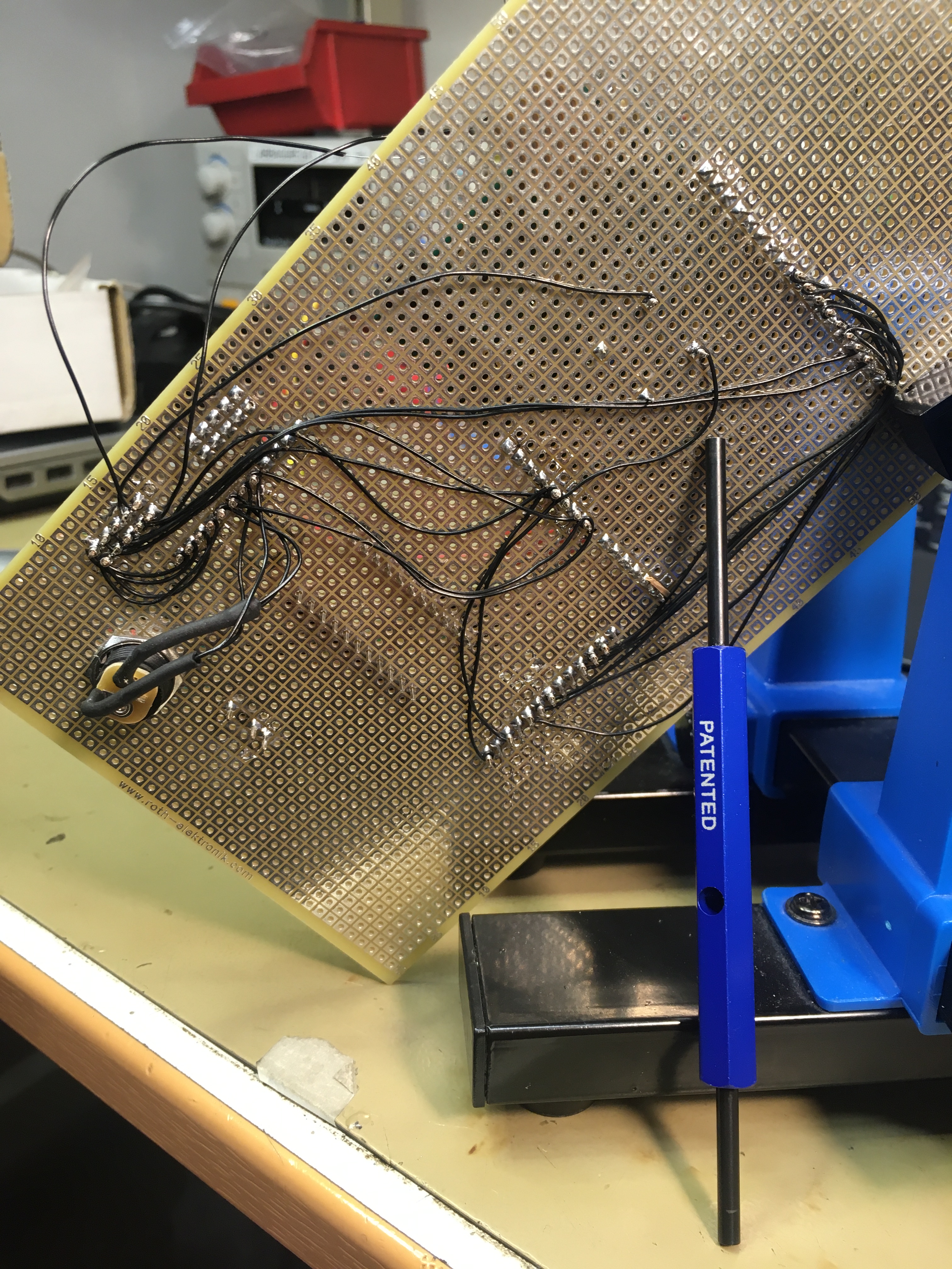
So over the summer, I have been working a bit at home (No kidding? This is 2020 after all :D). I also purchased a wire wrapping tool at an unbelievable 600SEK for something which is essentially a glorified screwdriver. But it really does its job!
What you see below is perhaps 10% of the wires that the final design will have. Not too pretty, but it clearly does the job. And with some planning, the final design could be really elegant.
So was it just all wiring and smiling faces? Of course not. My multimeter, as well as the identical one at the Makerspace, refuse to measure the forward voltage gap in the optocoupler LED, meaning I had no way of testing that the LED worked or that it was connected the right way. Very frustrating.
But rigging some wires and a resistor allowed me to check that the diode behaved properly and even gave readings on the detector photo transistor.
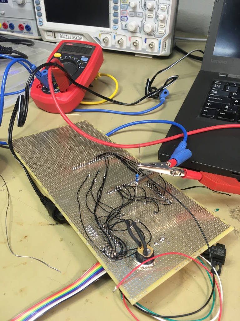
But when I did the final assembly, nothing at all worked. Since I could not test measure the LED once it was mounted on the proper cabling, it took me almost 2 hours to finally realize that there was a short on my motherboard. I thought I had tested all pins, but there was a tiny lead drop between two of the leg assembly connector pins. It took a full 3 seconds to remove it once I saw it….
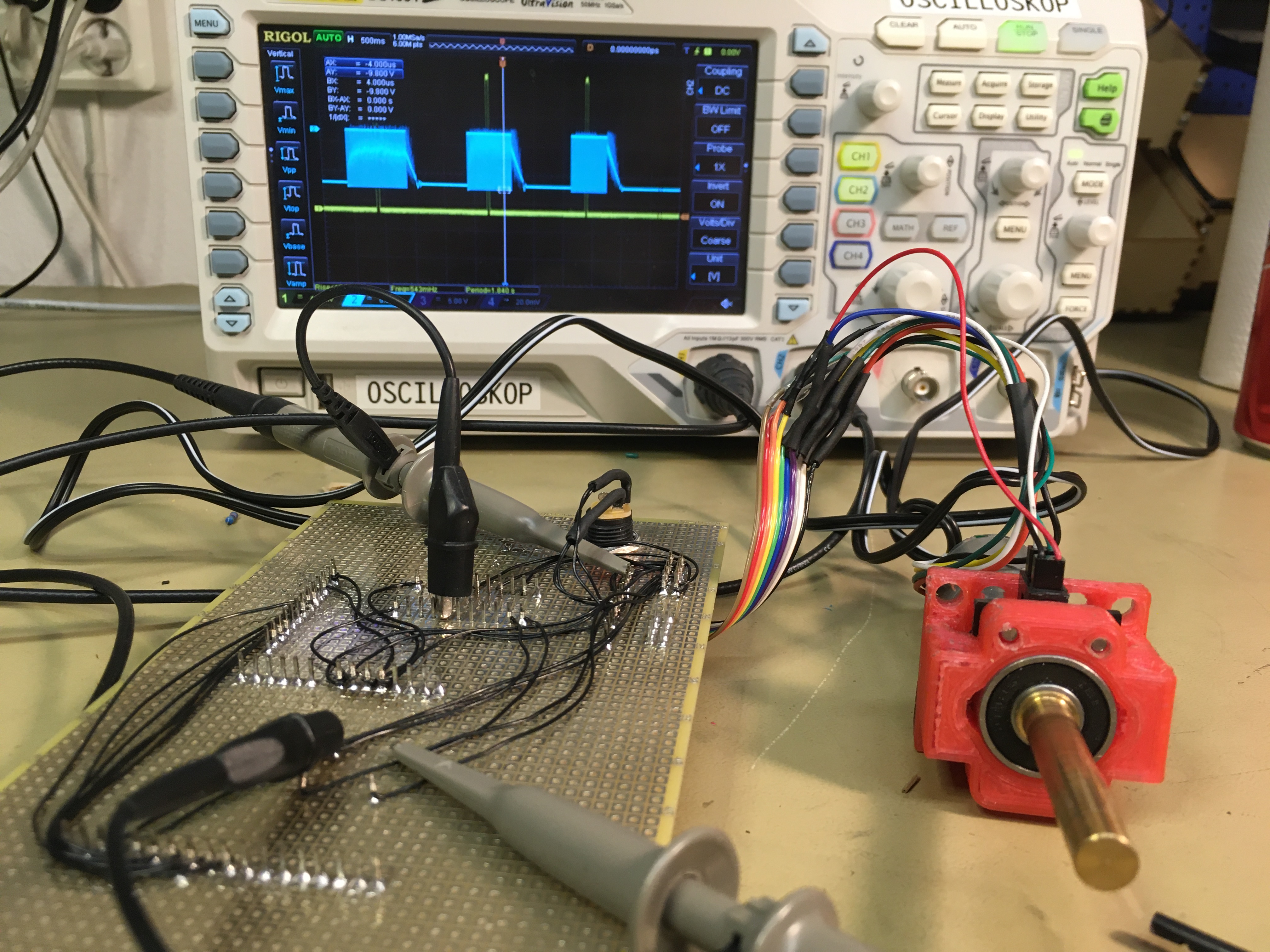
Here is me just trying to change all of my assumptions in order to find the error.
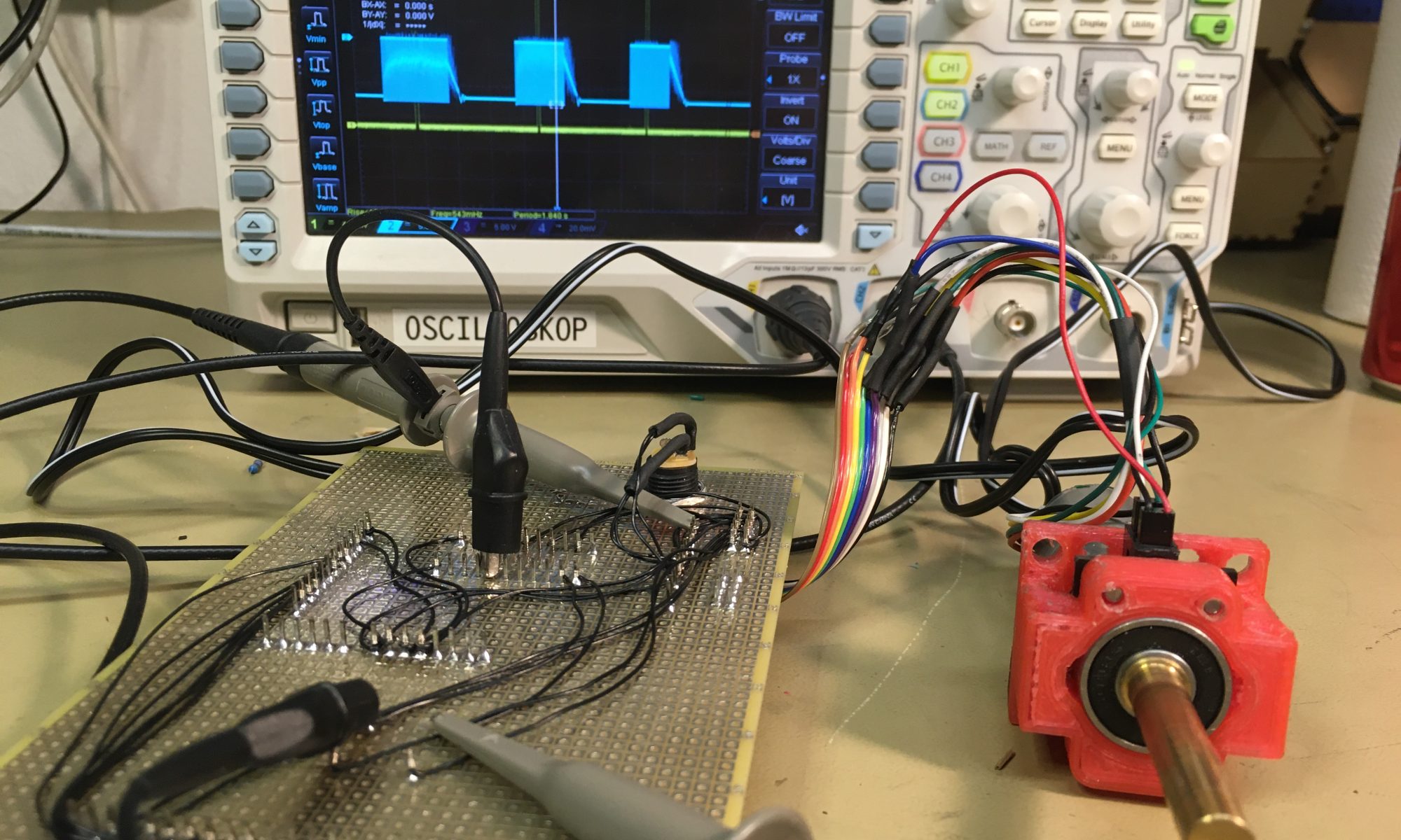
But once the short was removed, and I added some black electrical tape to the optobreaker plate since I printed it in transparent PLC, I could finally start my playground code and see the motor starting and stopping with a clear pulse from the optobreaker once every rotation.
It is nice to be awsome!
Now, the next step is to write the regulator code that allows nice clean control of the motor shaft.
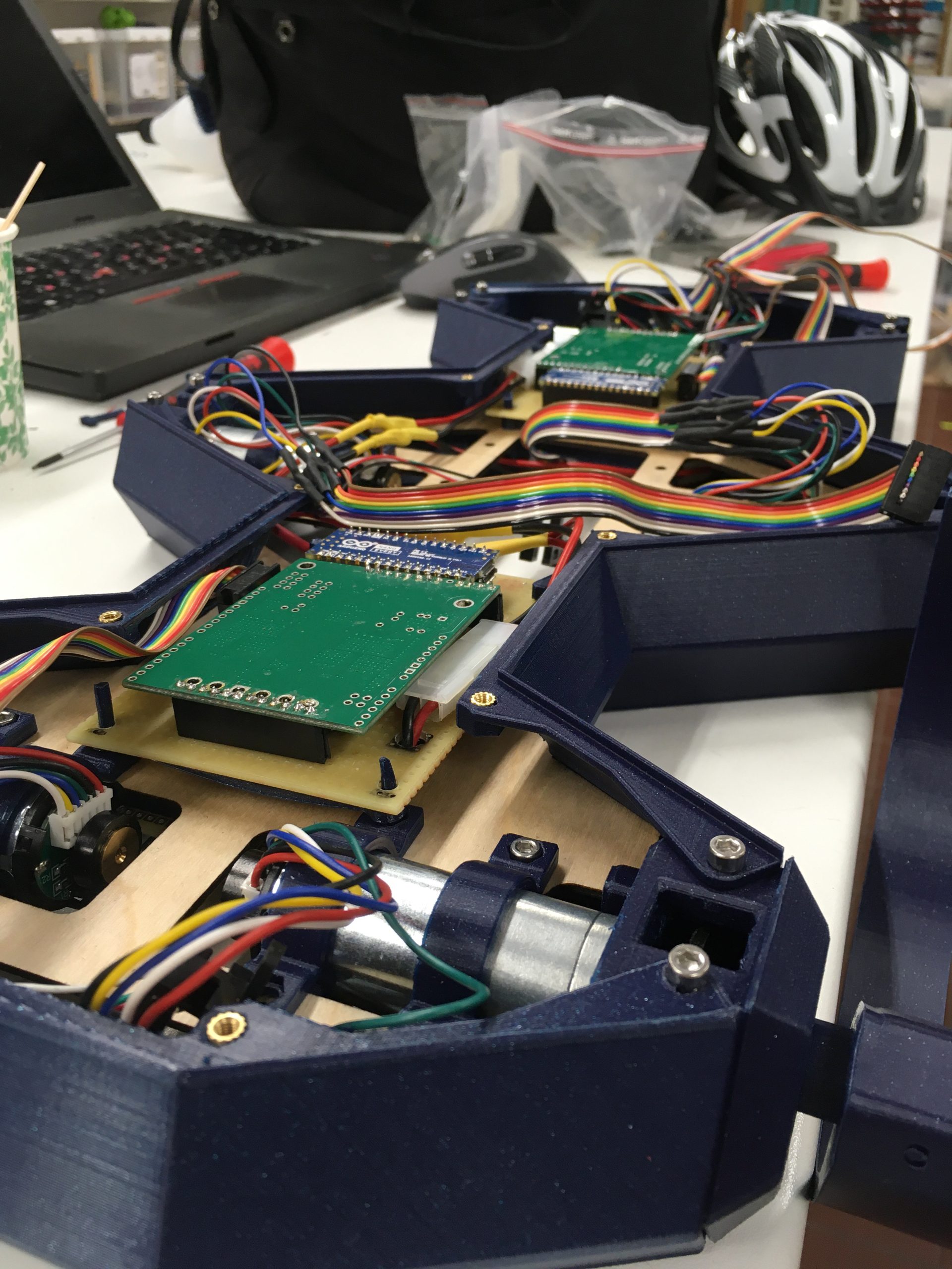
I also brought all parts home so I could mount all of the pieces, including the newly printed parts together at home and see if they all fit before next visit.